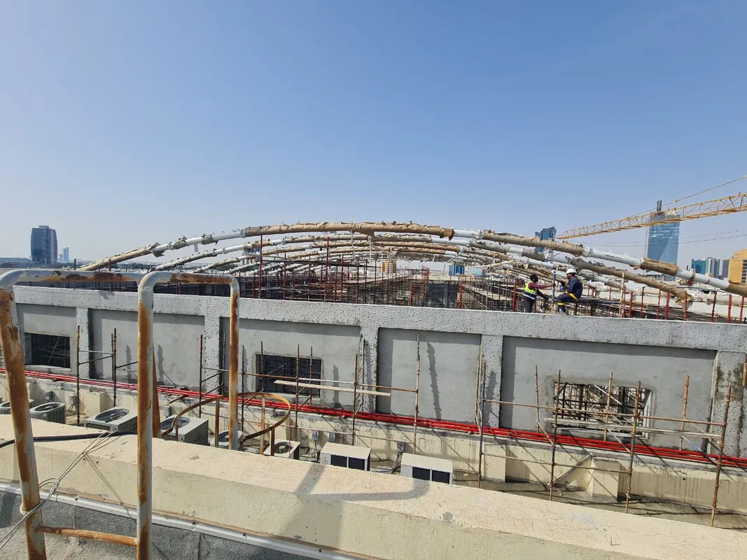
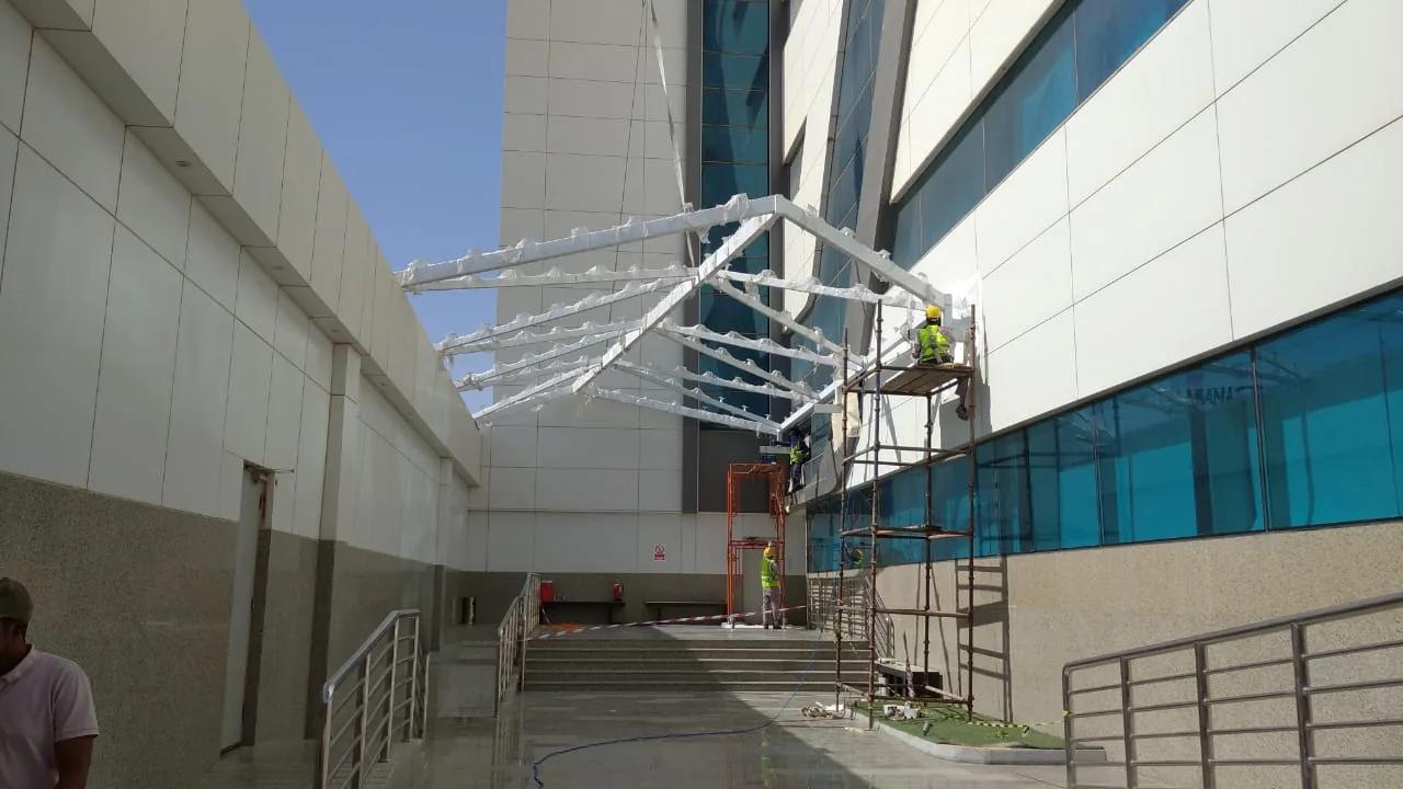
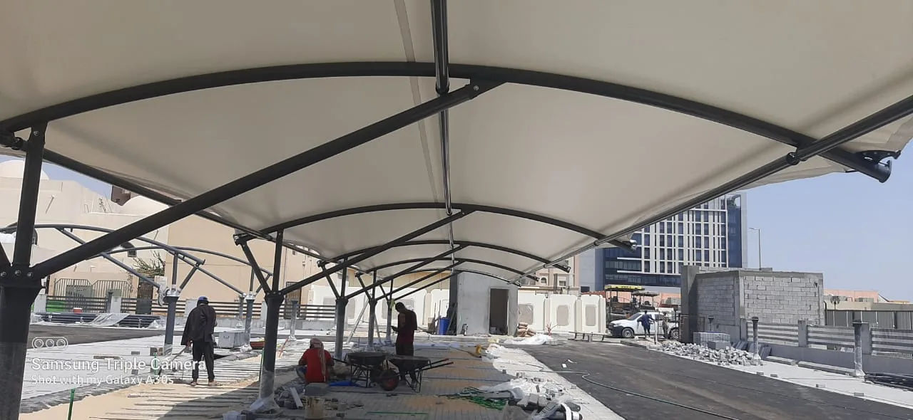
Brief Description — Structural Concept & Roof Geometry
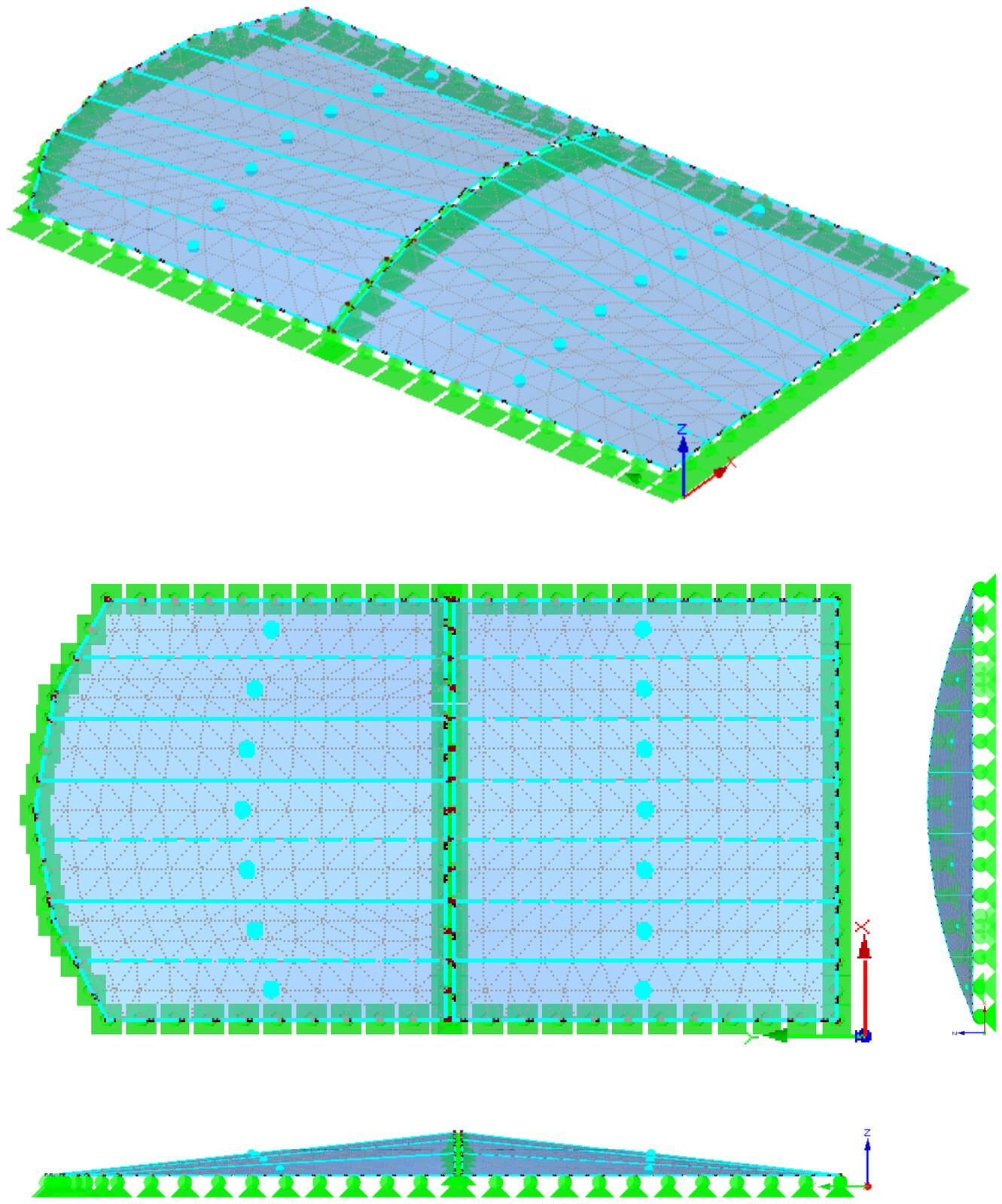
ETFE single layer, Khobar Saudi Arabia
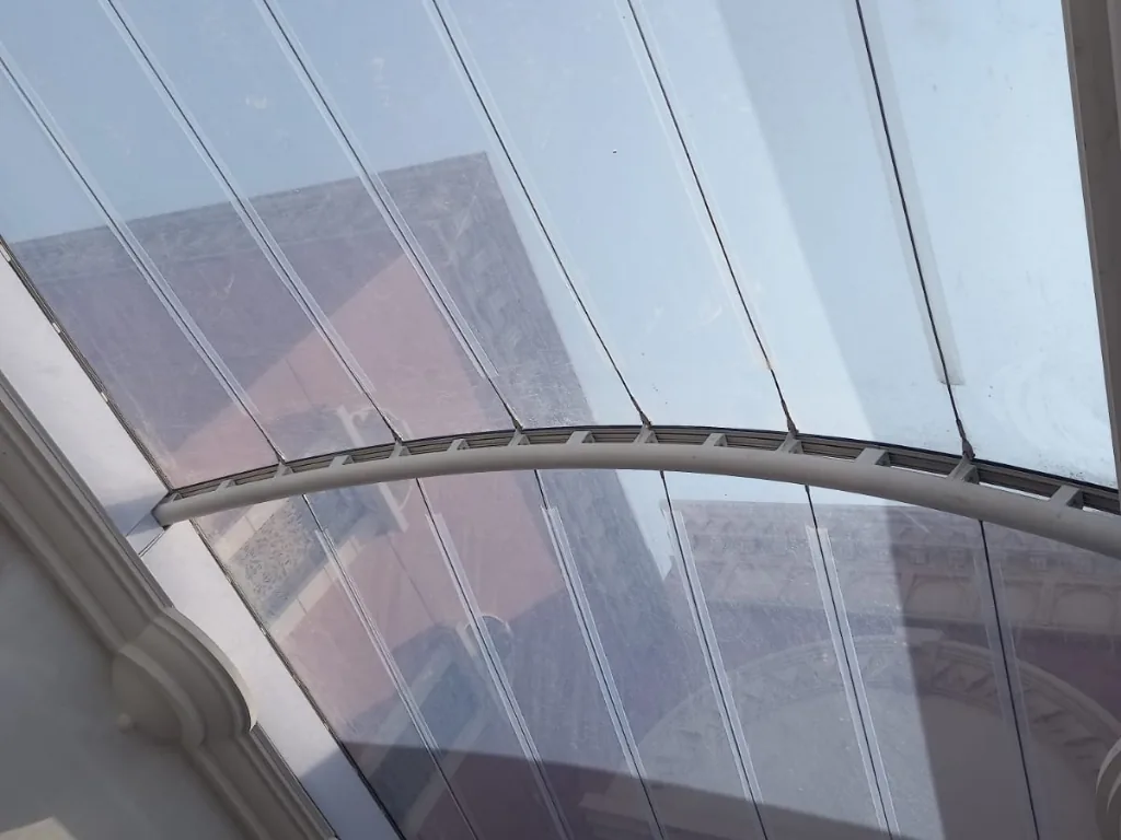
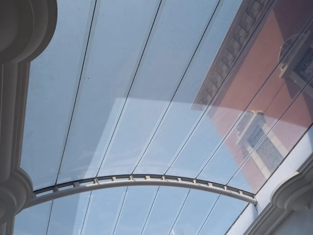
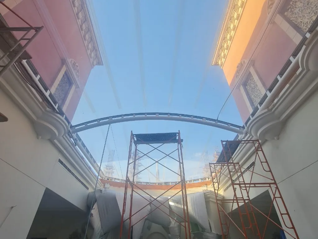
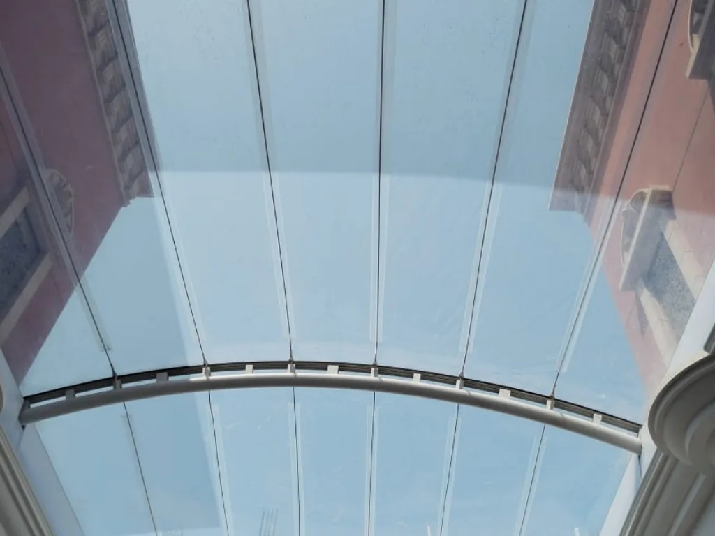
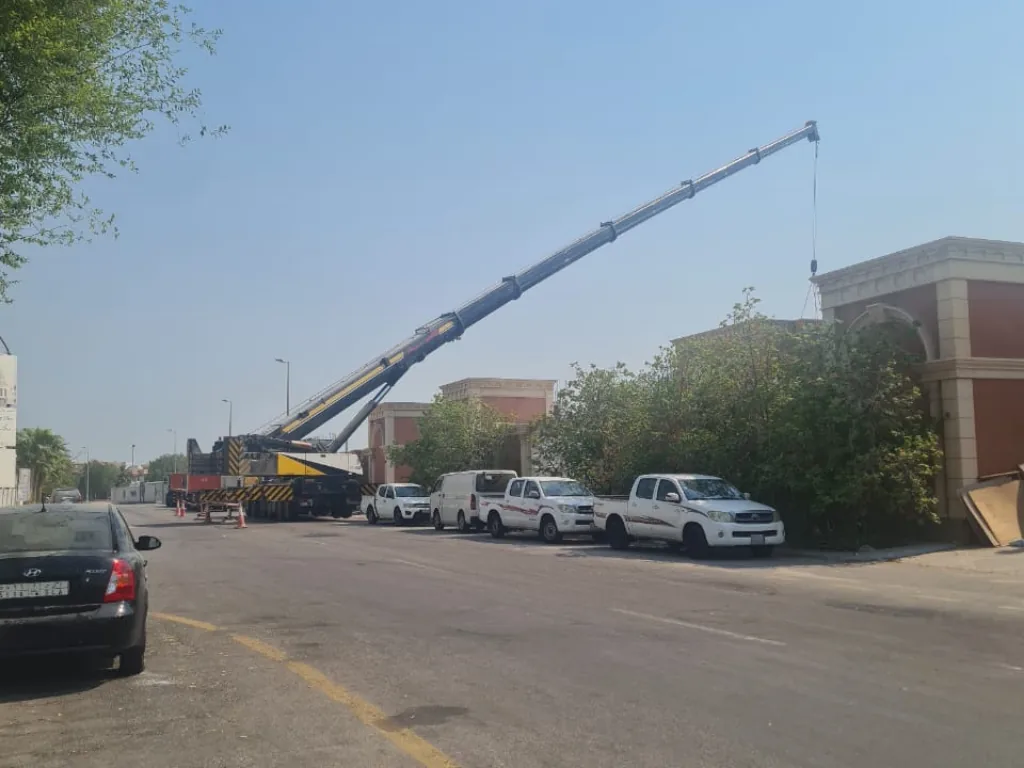
This private villa in Al Khobar has a courtyard roof of clear, un-printed single-layer ETFE covering more than 500 m². TMSI's scope was design, supply and installation, and the project is dated 2023.
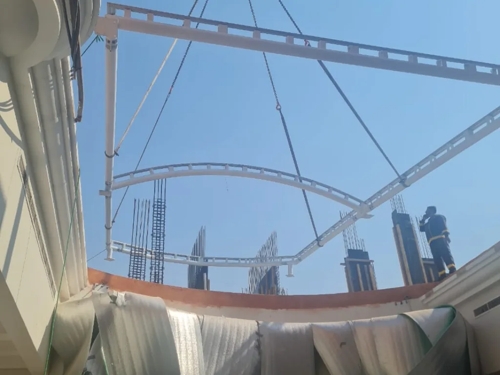
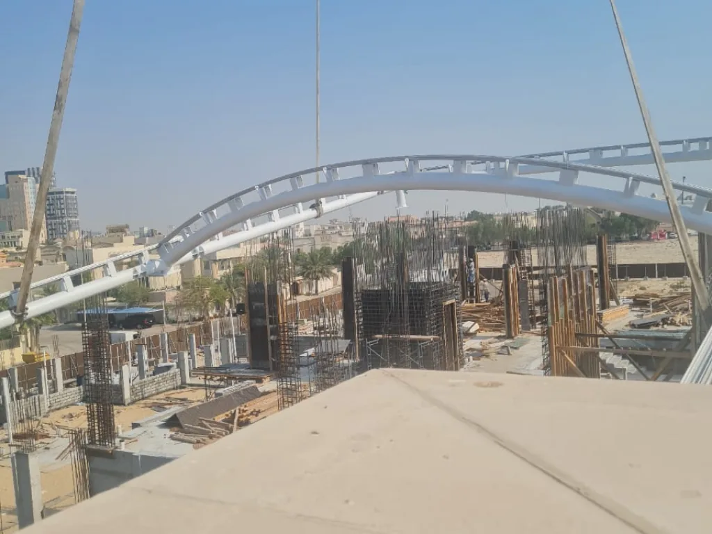
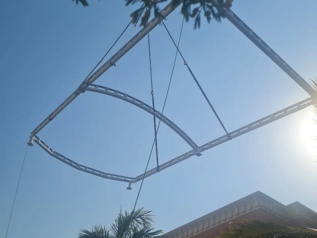
The clear foil was chosen to bring as much daylight as possible into the enclosed courtyard. The membrane sits on curved tubular steel arches that were rolled and welded in the TMSI factory, and a stainless steel cable net runs with the curvature to control deflection under wind uplift. An integrated aluminium perimeter clamping system holds the foil and provides a continuous water seal.
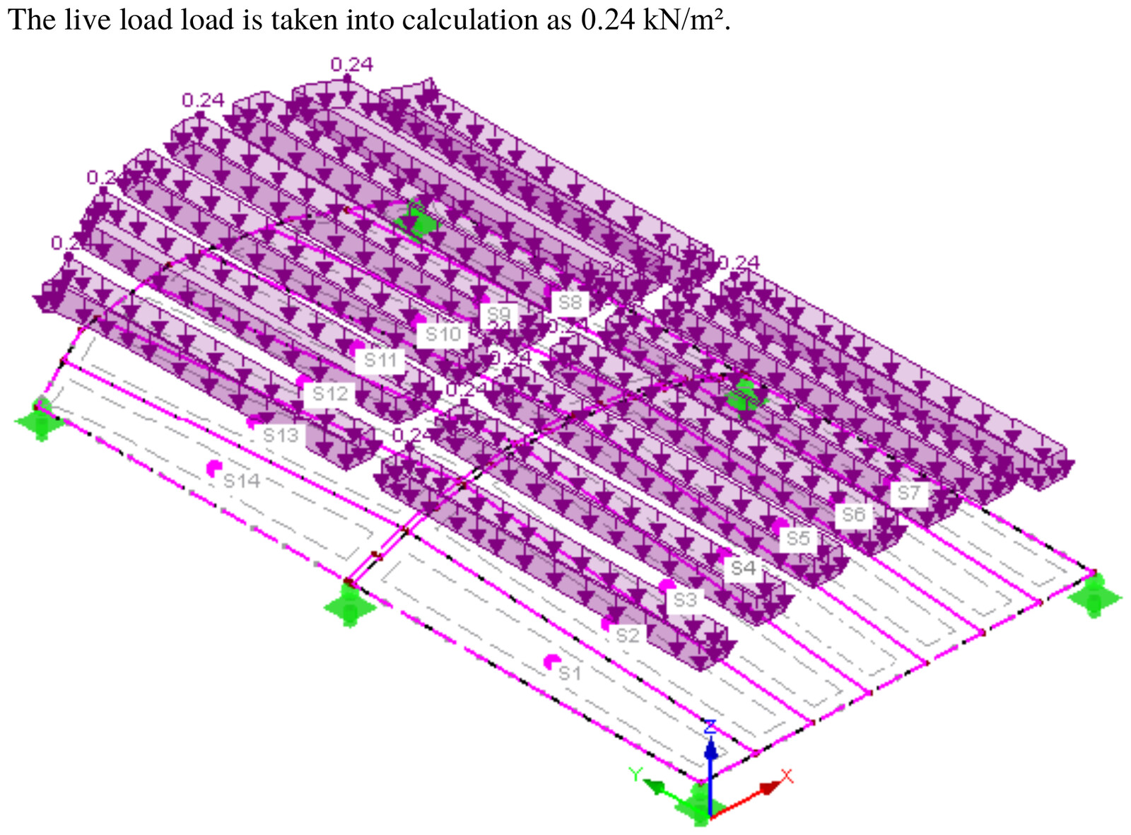
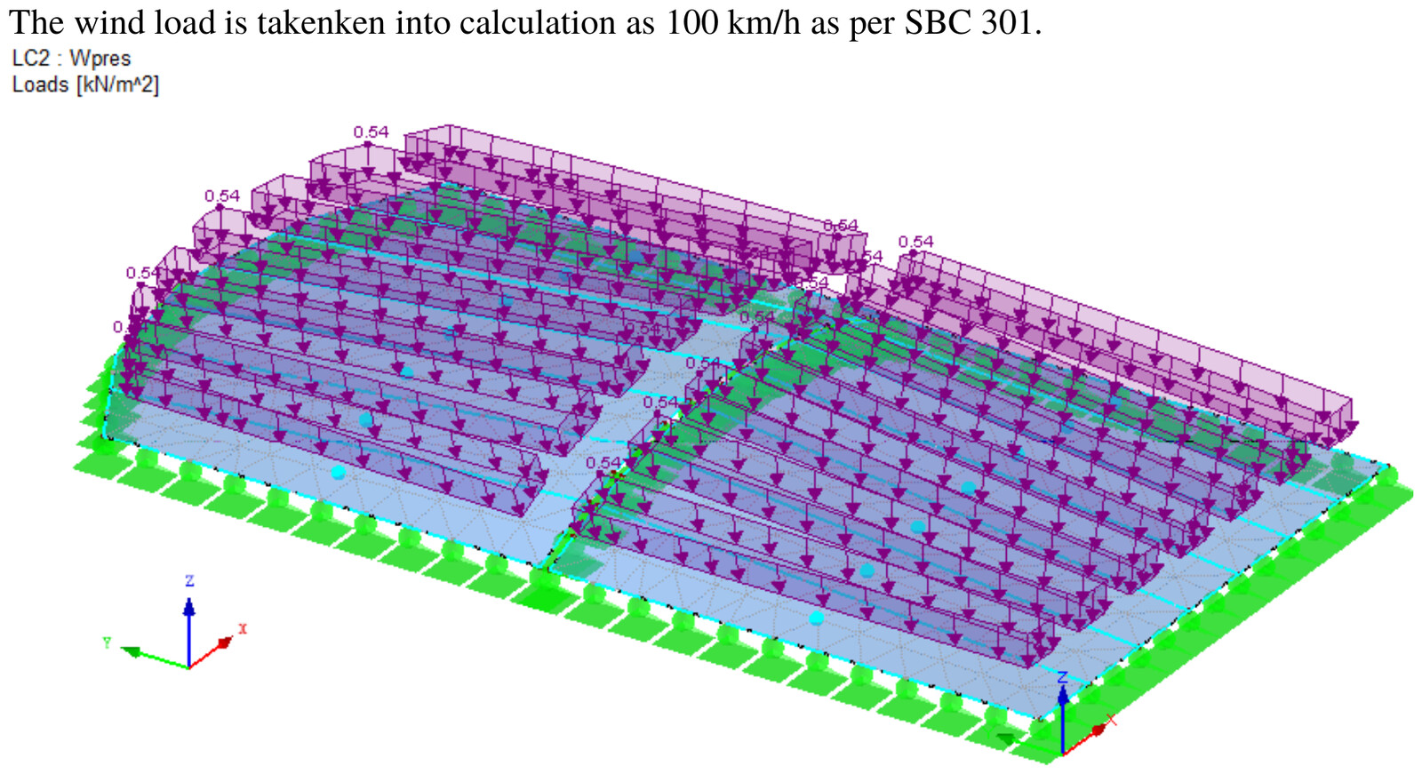
Because it is a single-layer system, the roof has no mechanical plant and no power requirement — a passive, low-maintenance installation. The roof geometry was set by form-finding and analysed for wind, uplift and thermal load; panels were then patterned, thermally welded and inspected in the Dammam factory before being installed, tensioned, sealed and water-tested on site, with curvature checked so that no ponding can occur.

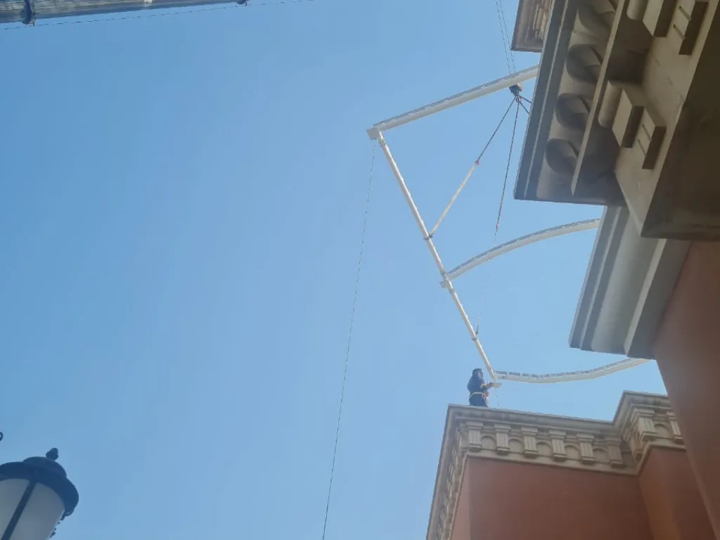
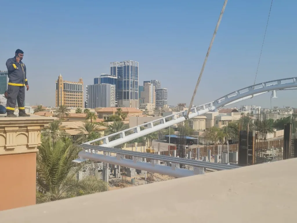
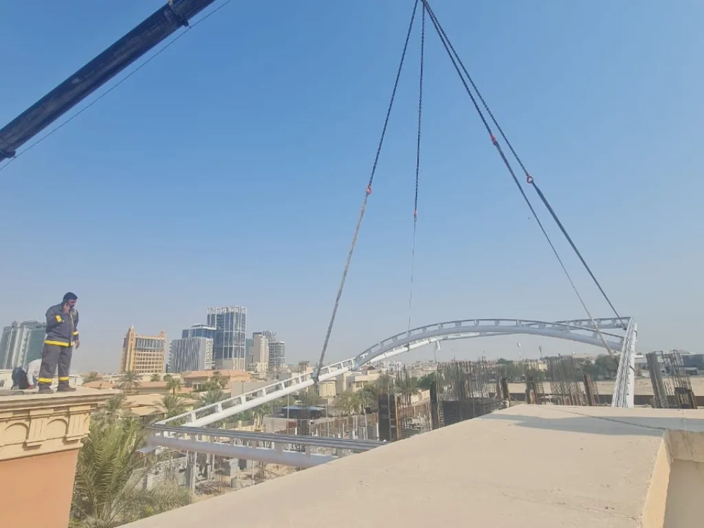
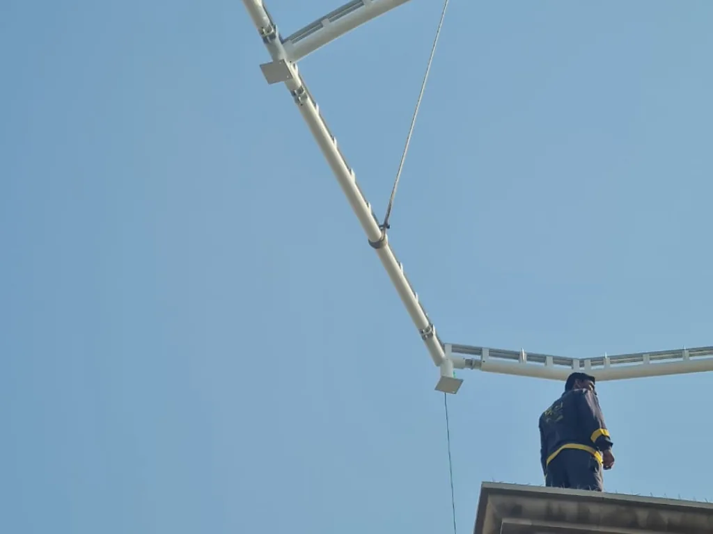
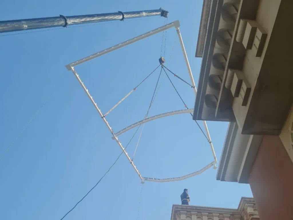
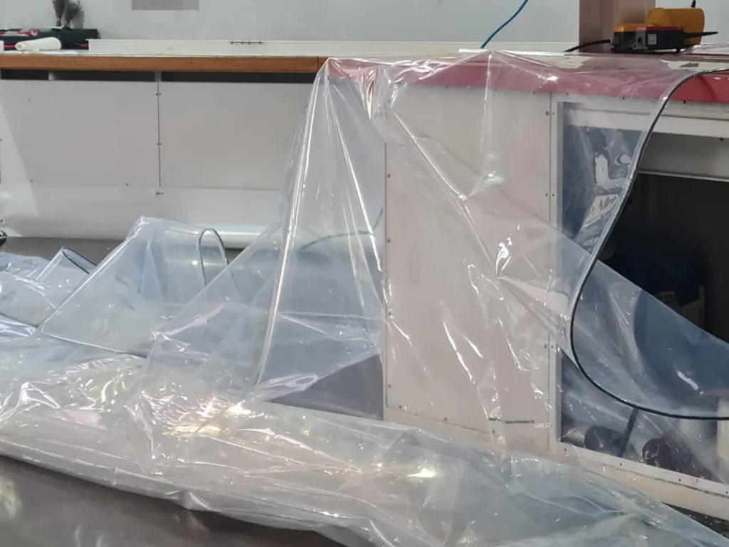
PROJECT 01
| Project | Private Villa |
|---|---|
| Location | Al Khobar, Saudi Arabia |
| System | ETFE single layer, clear |
| Approx. area | 500+ m2 |
| Foil finish | Clear, un-printed |
| Restraint | Stainless steel cable net |
| Structure | Curved tubular steel arches |
| Scope | Design, supply and install |
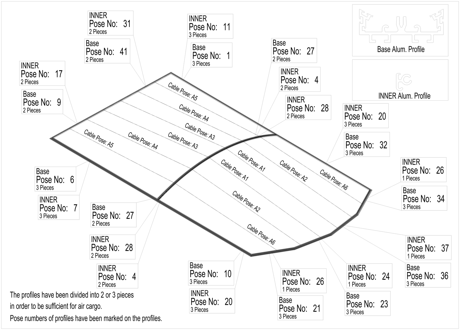
Every panel is engineered, patterned and welded in our Dammam factory, then delivered to site as a finished, numbered assembly. The sequence below follows the actual production and installation route used on this project.
DESIGN & ENGINEERING
| Node No. | LC/CO | Support Forces [kN] | Support Moments [kNm] | ||||
|---|---|---|---|---|---|---|---|
| P X' | P Y' | P Z' | M X' | M Y' | M Z' | ||
| CO47 | 0,43 | 28,23 | -6,86 | 0,00 | 0,00 | 0,00 | |
| CO48 | -5,13 | 30,94 | -7,40 | 0,00 | 0,00 | 0,00 | |
| CO49 | 0,43 | 28,23 | -6,86 | 0,00 | 0,00 | 0,00 | |
| Definitions | Symbol | Unit | Value | Formulation |
|---|---|---|---|---|
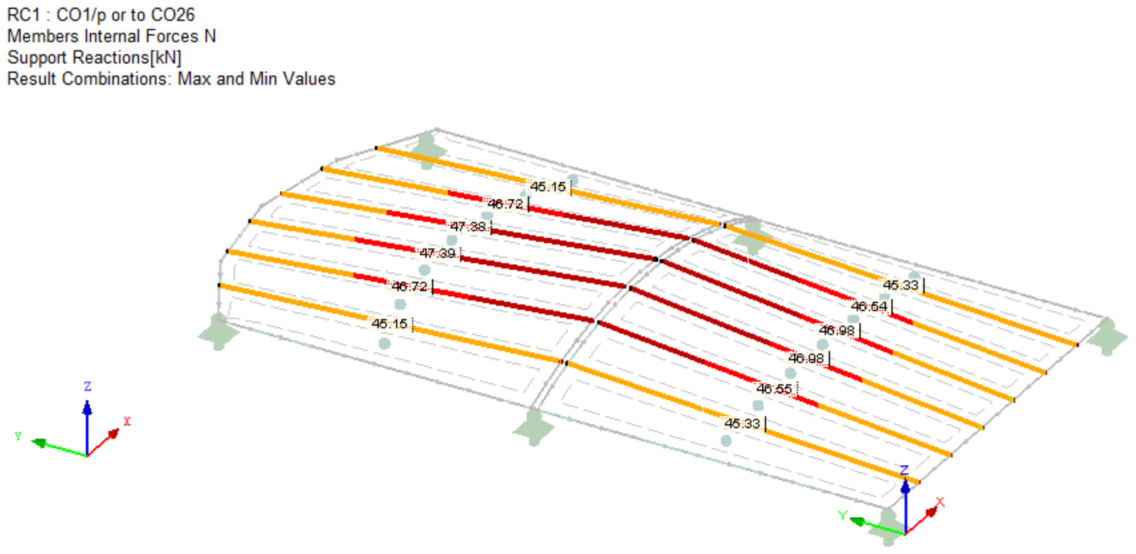
| Cable tension | Nges | [kN] | 47,39 | |
| Quantity of cables | n | [-] | 1 | |
| Cable tension in the single cable | Nseil | [kN] | 47,39 | |
| Design Criteria | LRFD | |||
| Load Safety Factor | γf | [-] | 1,00 | |
| Material Safety Factor | γR | [-] | 1,00 | (usually 1.0) |
| Cable Type | 1x19 | |||
| Cable Diameter | d | [mm] | 12 | |
| Tensile Strength | Rr | [N/mm²] | 2160 | |
| Youngs Modulus for variable action | EQ | [kN/cm²] | 15000 | |
| Filling load factor | f | [-] | 0,760 | |
| Equavalent Diameter Factor | fed | [-] | 0,872 | |
| Equavalent Diameter (Sap2000) | de | [mm] | 10,46 | =de*fed |
| Reduction dirilling | k | [-] | 0,880 | |
| Self Weight factor | w | [kg/cm²] | 0,830 | |
| Breaking Load Factor | K | [-] | 0,525 | = pi*f*k/4 |
| Metallic Cross Sectional Area | Am | [cm²] | 0,860 | |
| Nominal Metallic Areac Factor | C | [-] | 0,600 | |
| Stifness Single Cable | EA | [MN] | 12,893 | |
| Stifness All cables | EAges | [MN] | 12,893 | |
| Cable Weight | g | [kg/m] | 0,71 | =Am*w |
| Minimum Breaking Load Cable | Fmin | [kN] | 124,1 | = K*d2*Rr/1000 |
| Socet Type | Swaged Socket | |||
| Loss factor (Due to cable fitting) | ke | [-] | 0,90 | |
| Characteristic value of the resistance | Fuk | [kN] | 121,0 | =Fmin*ke |
| Design Value of the cable tension | FEd | [kN] | 47,39 | =Nseil*γf |
| Design value of the cable resistance | Frd | [kN] | 80,67 | =Fuk/1.5*γR |
| Verification in the ultimate limit state | Fed/Frd | [-] | 0,59 | OK |
Cables 12 mm stainless steel.
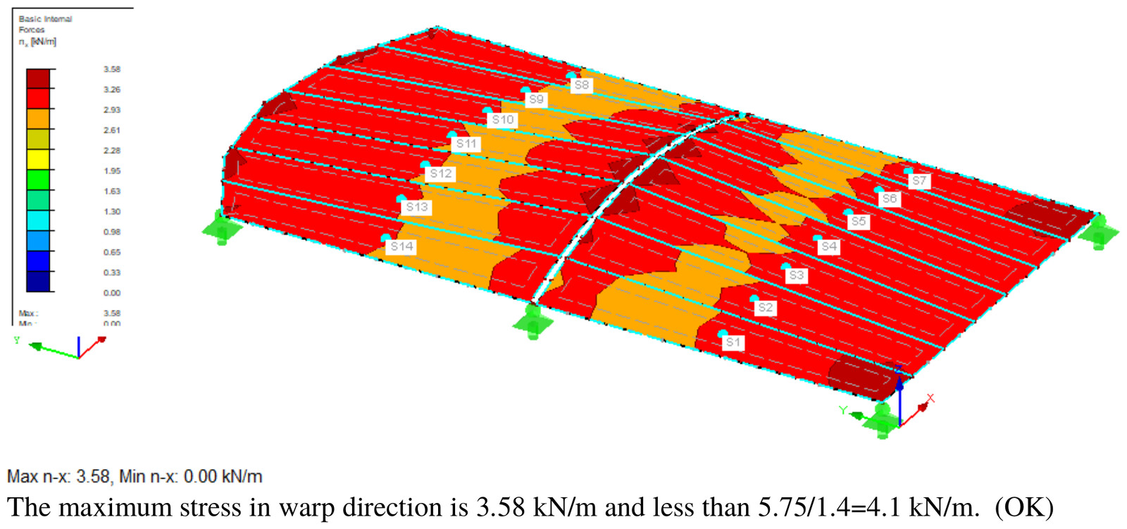
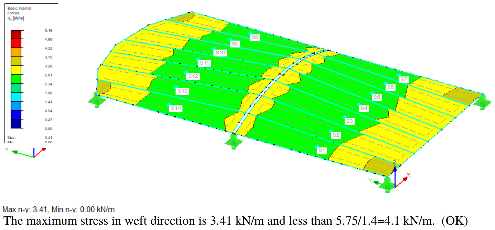
This means ideally that the pretension in single layer ETFE foil structures should not exceed 3 MPa (for 250 micron 0.75 kN/m) and permanent high load like snow should be avoided. The breaking strength of ETFE foil is 50 MPa. However the elongation at the tensile strength level (tensile strain at break) is 500%. That’s why the breaking strength can not be used for design. In the design tensile stress at 10 % strain has been taken into account (23 MPa). The thickness of ETFE foil is 0.25 mm (250 micron). For 250 micron foil, the tensile stress at 10 % strain equals to 5.75 kN/m. The safety factor is taken into account as 1.5 for short term load (e.g. wind loading).
| PROPERTY | TEST METHOD | UNIT | MEAN VALUE |
|---|---|---|---|
| General | |||
| Specific Gravity | ASTM D 792 | g/cm³ | 1.75 |
| Optical (200 µm film, clear) | |||
| Light Transmission | DIN EN 410 | % | > 91 |
| Colour Rendering Index | DIN EN 410 | - | 98.8 |
| Shading Coefficient | DIN EN 410 | - | 1.063 |
| Solar Heat Gain Coefficient | DIN EN 410 | - | 0.925 |
| Mechanical | |||
| Tensile Strength | DIN EN ISO 527-1 (MD/TD) | MPa | 50 |
| Tensile strain at break | DIN EN ISO 527-1 (MD/TD) | % | 500 |
| Tensile stress at 10 % strain | DIN EN ISO 527-1 (MD/TD) | MPa | 23 |
| Tensile Modulus (0,05-1%) | DIN EN ISO 527-1 (MD/TD) | MPa | 1000 |
| Tear resistance | DIN 53363 (MD/TD) | N/mm | 400 |
| Thermal | |||
| Thermal Service Range | °C | -200 - 150 | |
| Melting Point | ASTM D 4591 | °C | 265 |
| Shrinkage 150 °C/10 min | % | 0 - 5 |
Send us the area, the city and the fabric you need — we come back with a system and an indicative budget.