Brief Description — Structural Concept & Roof Geometry
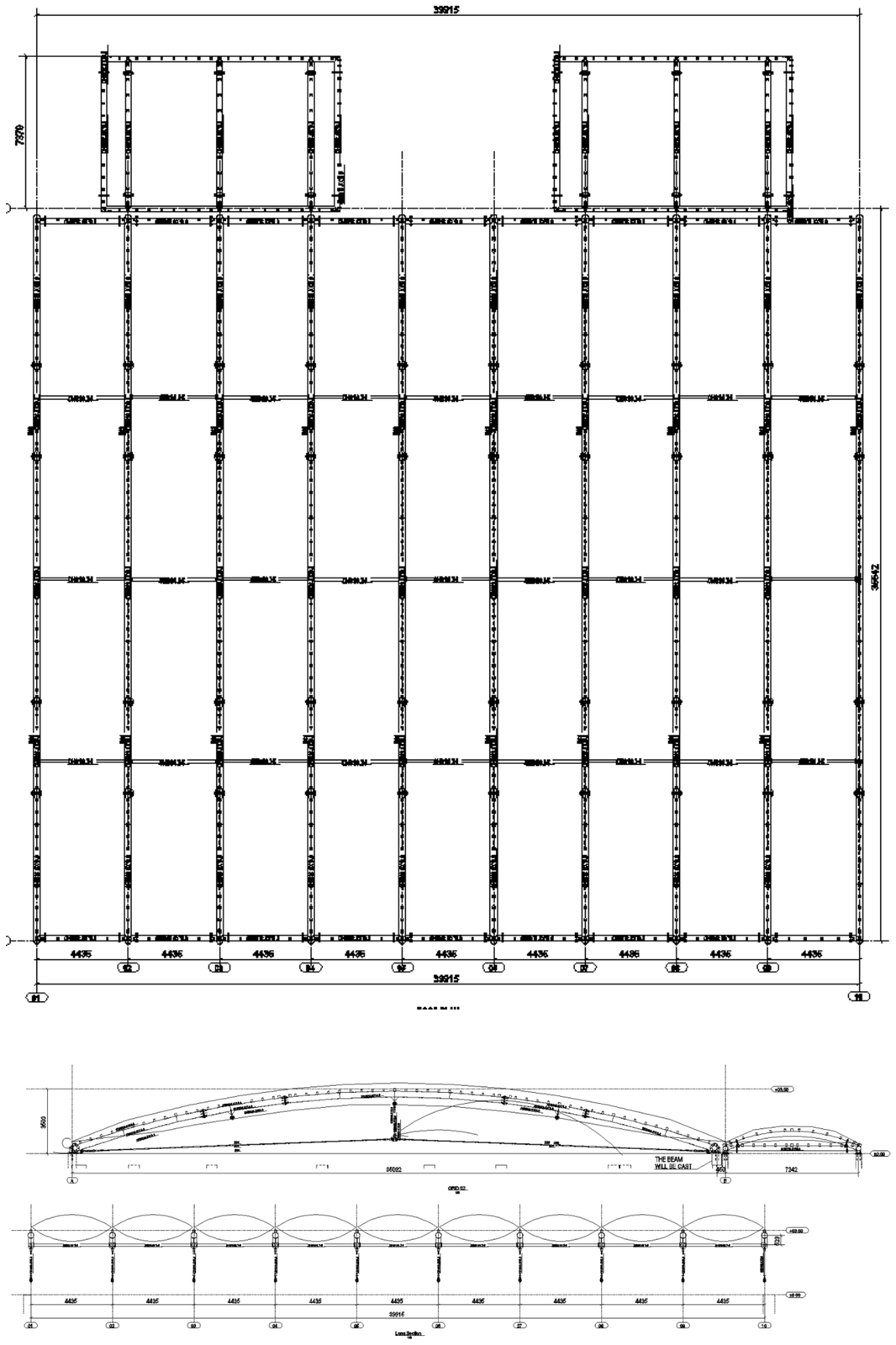
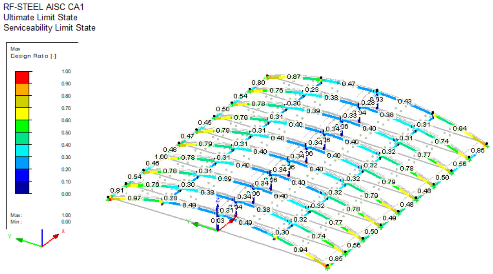
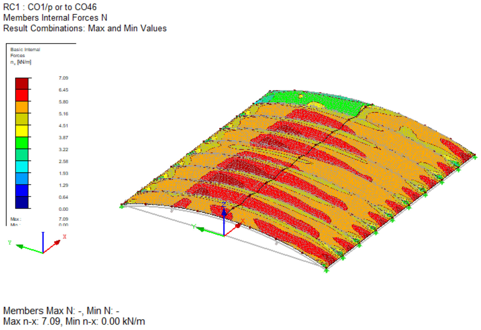
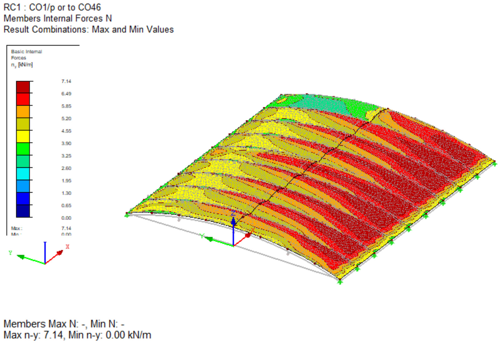
For the ETFE structures, this pre calculation report has been prepared. The aim of the pre calculation report is to check the conceptional design of structure and load conditions.
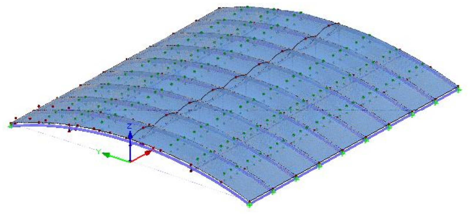
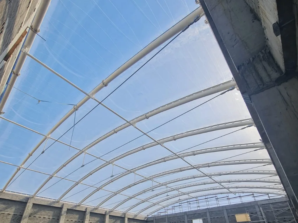
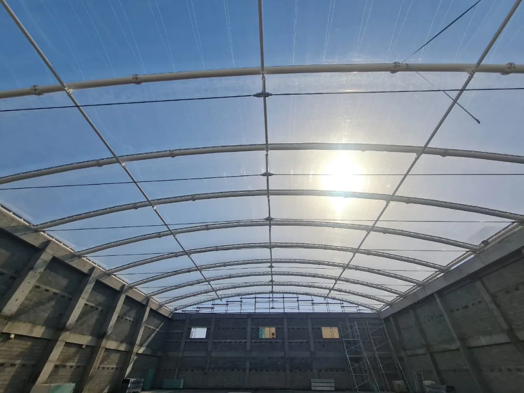
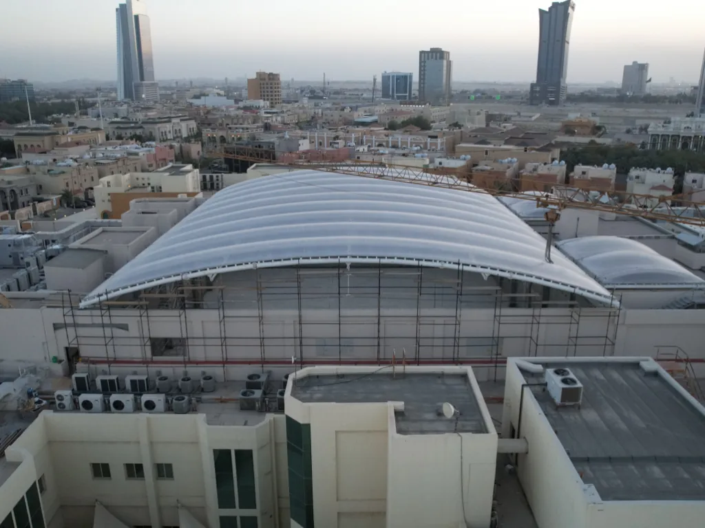
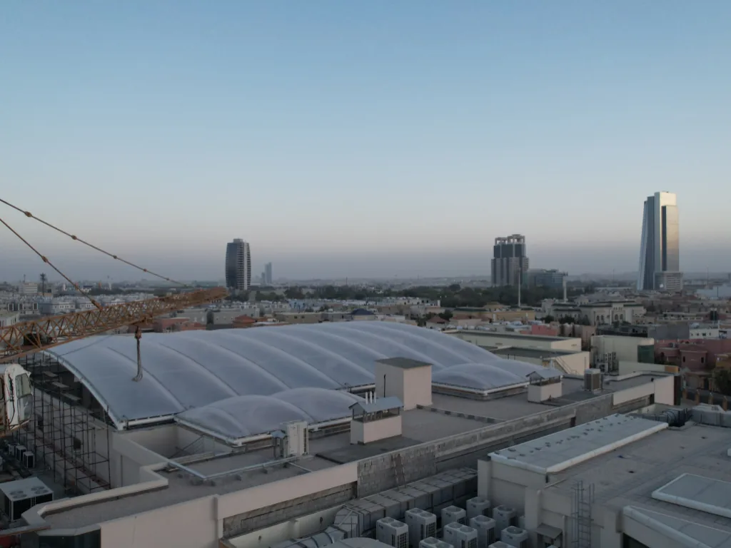
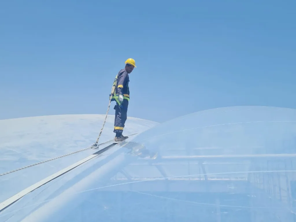
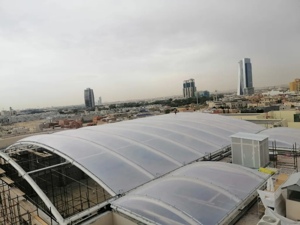
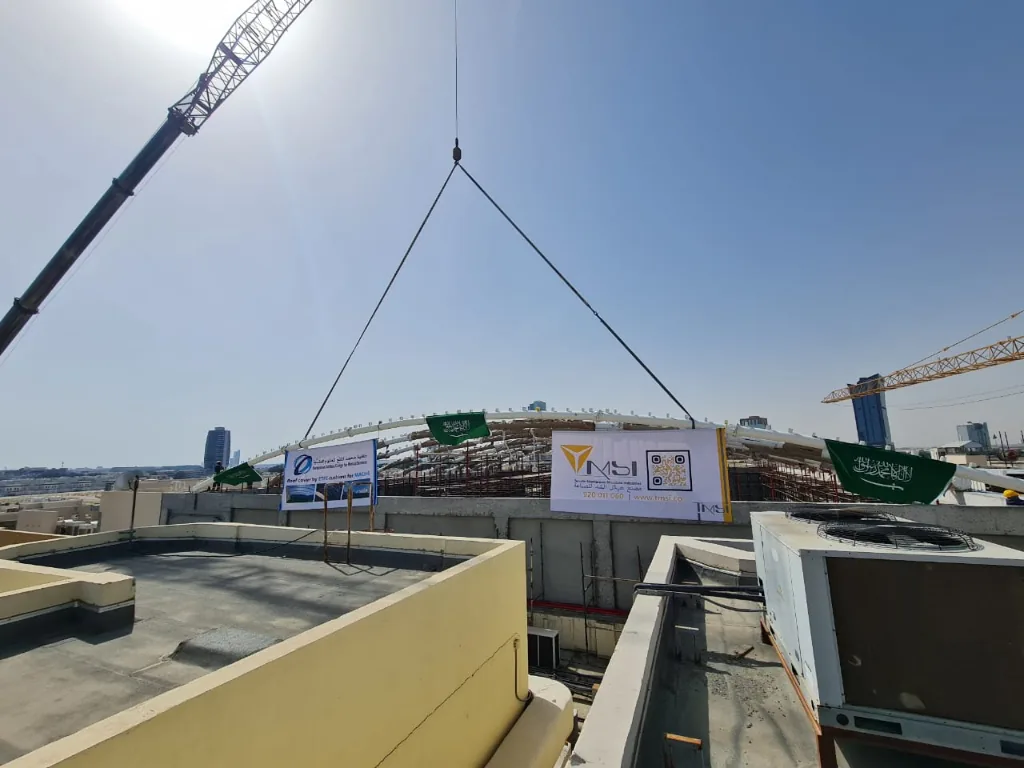
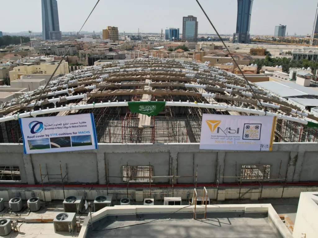
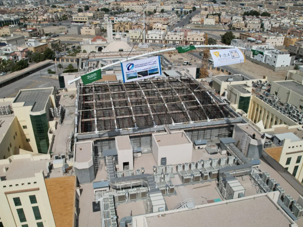
Roof cover by ETFE cushions for MACHS
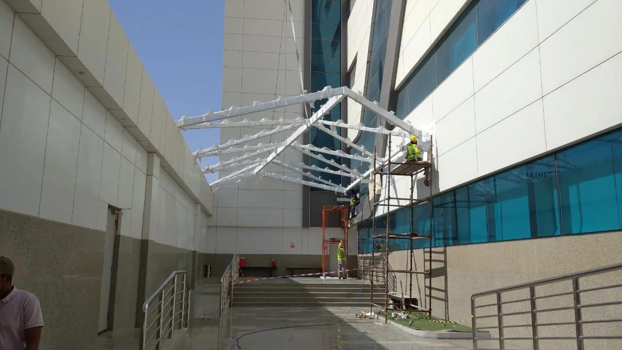
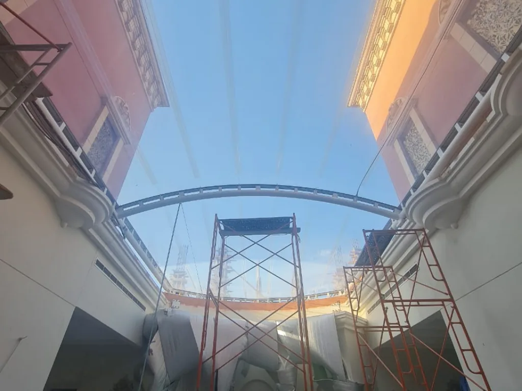
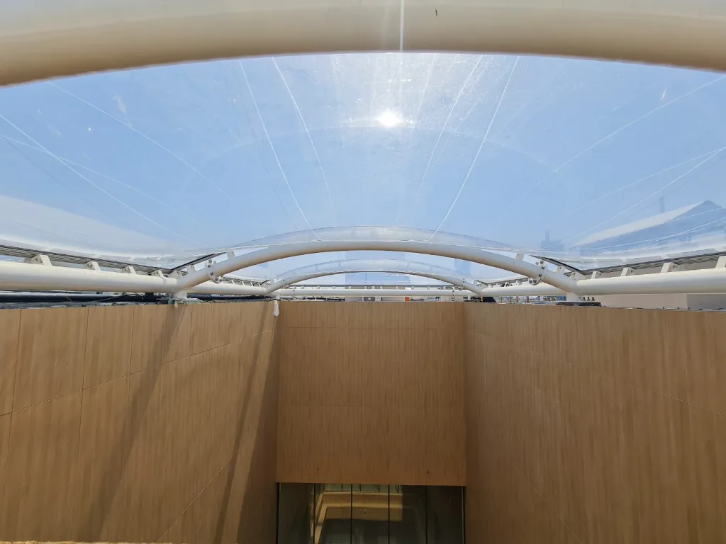
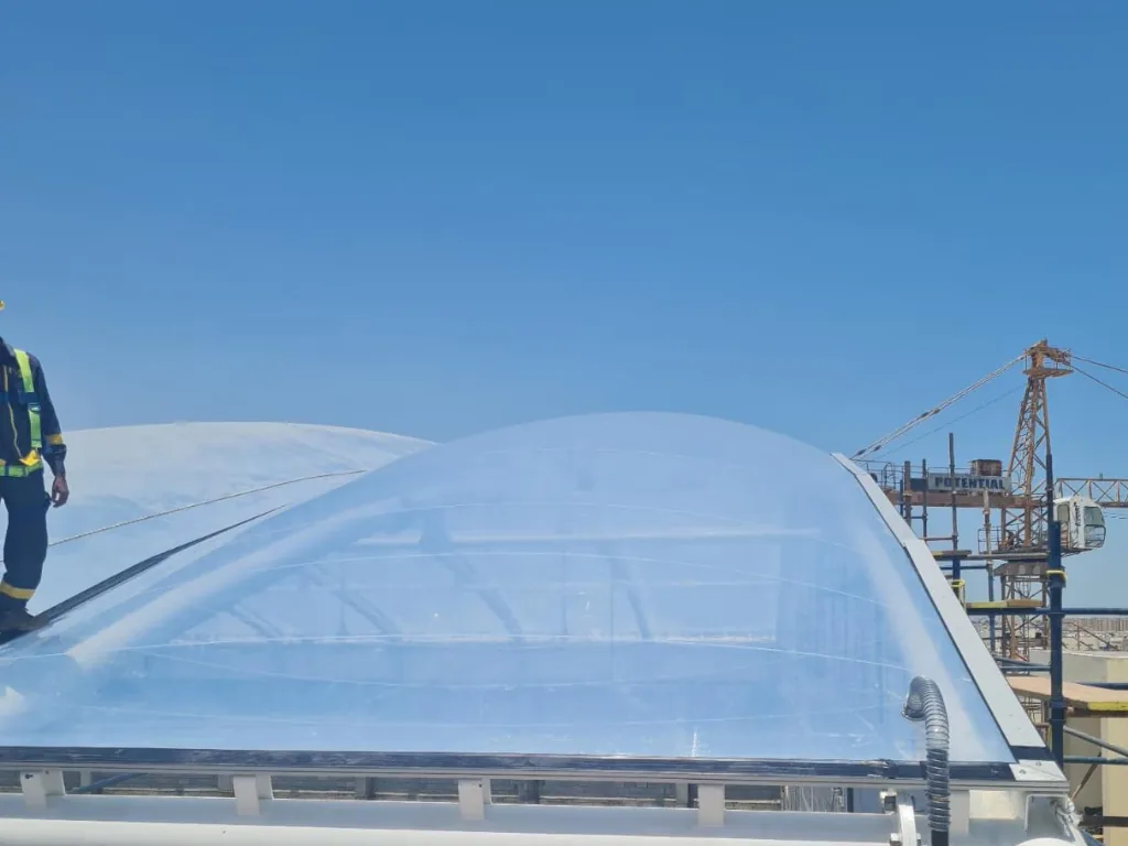
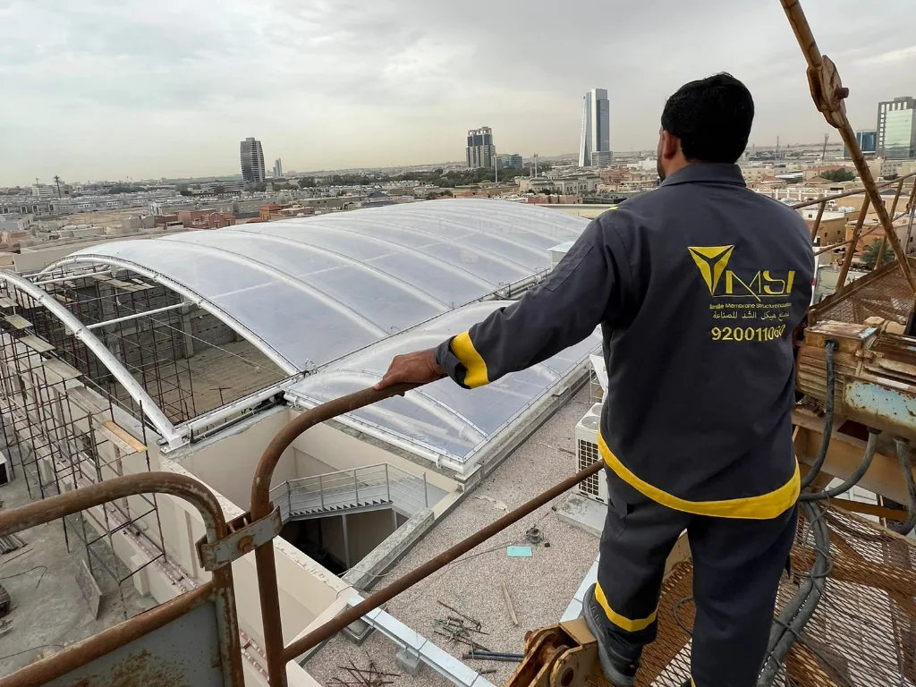
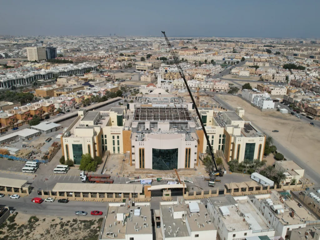
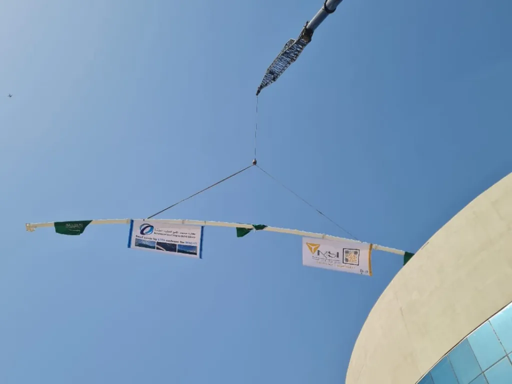
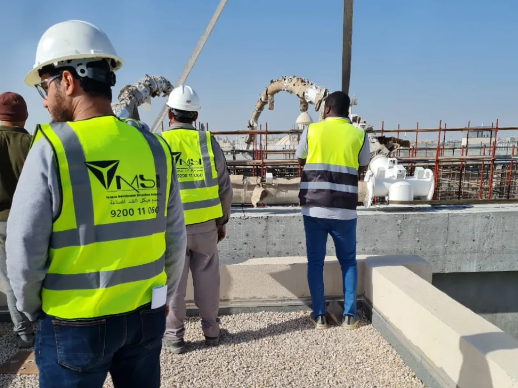
The MACHS Stadium is the sports stadium of Mohammed Al-Mana College for Health Sciences (MACHS) in Dammam. Its long-span arched roof is built from double-layer ETFE cushions covering more than 1,500 m². TMSI's scope was design, supply and installation, and the project is dated 2023.
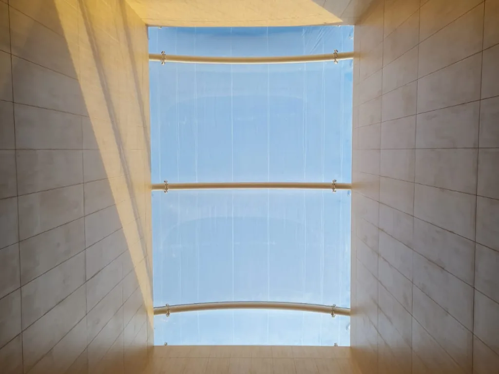
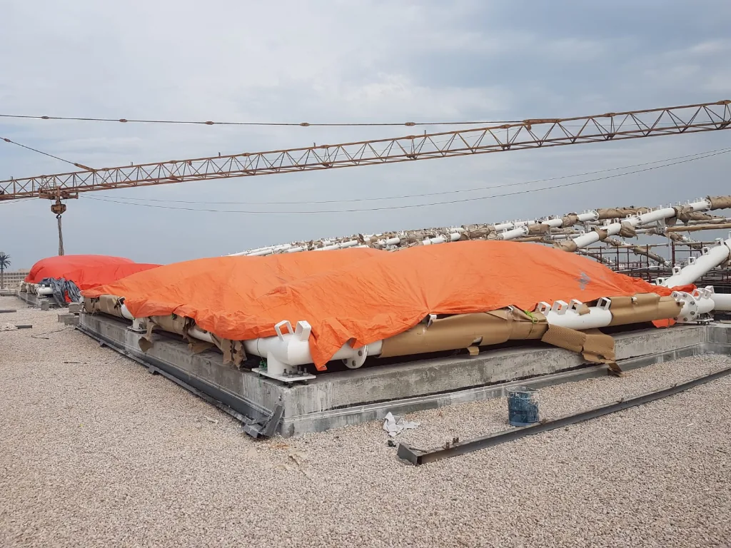
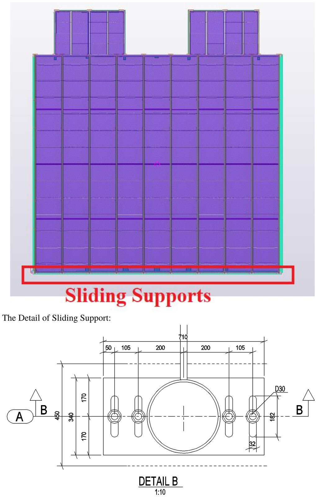
The cushions are held permanently at 250–300 Pa by an air handling unit with two fans for load sharing and redundancy; non-return valves hold pressure in the system. The trapped air gives the roof its stiffness and an insulating cavity, with a U-value of approximately 2.9 W/m²K for the two-layer build-up. The cushion grid was laid out so that no rectangular cushion exceeds the 3.5 m guideline span, and individual cushions can be replaced without disturbing the rest of the roof.
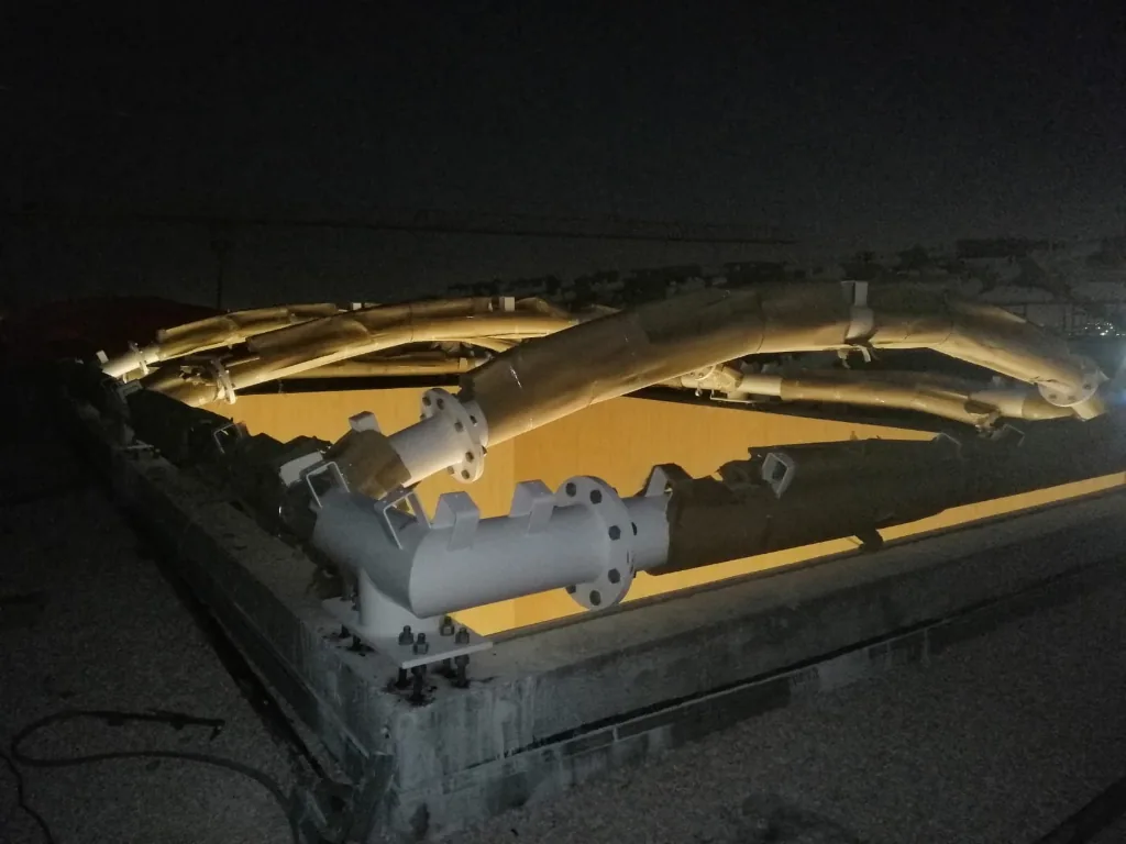
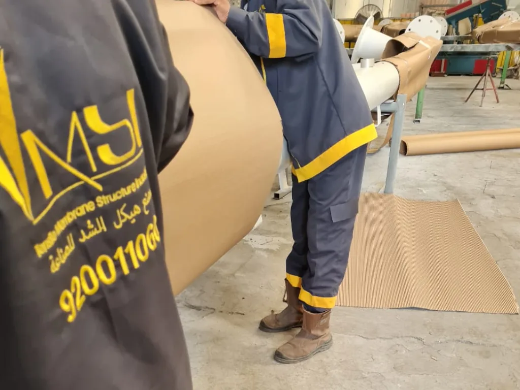
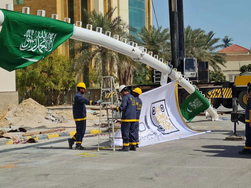
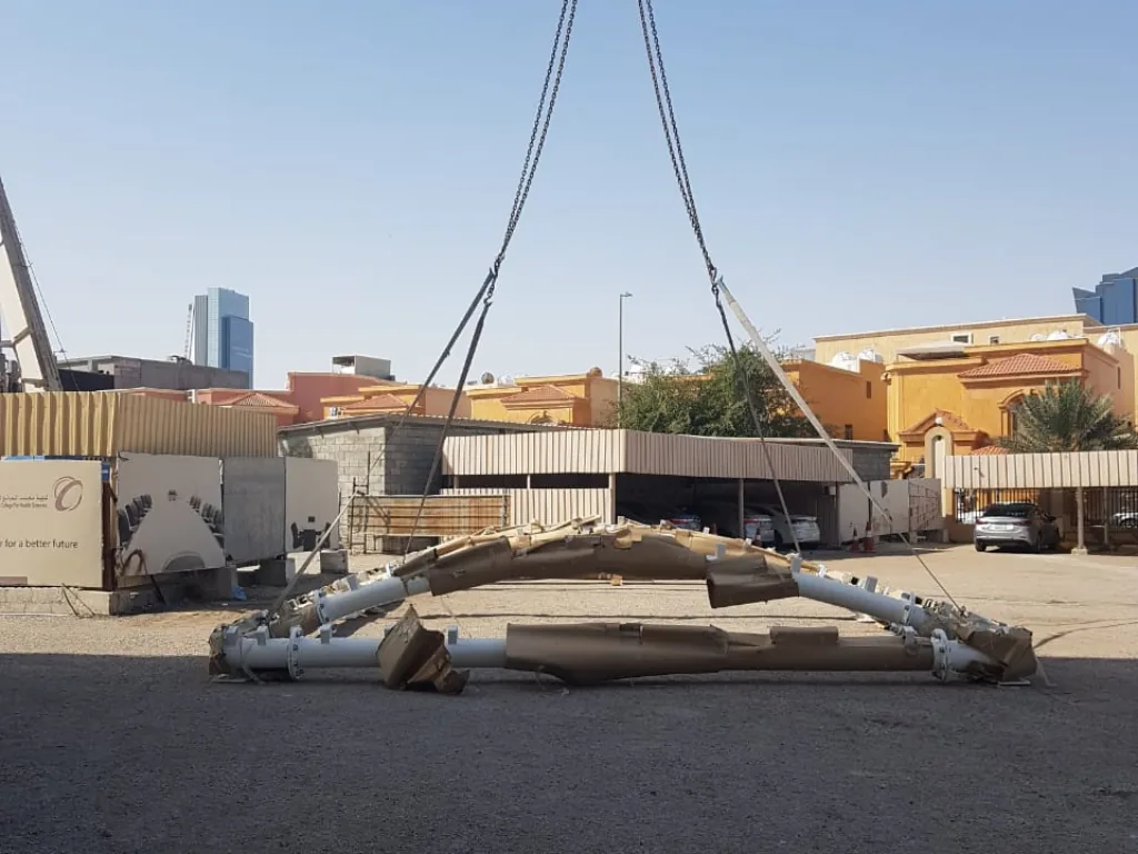
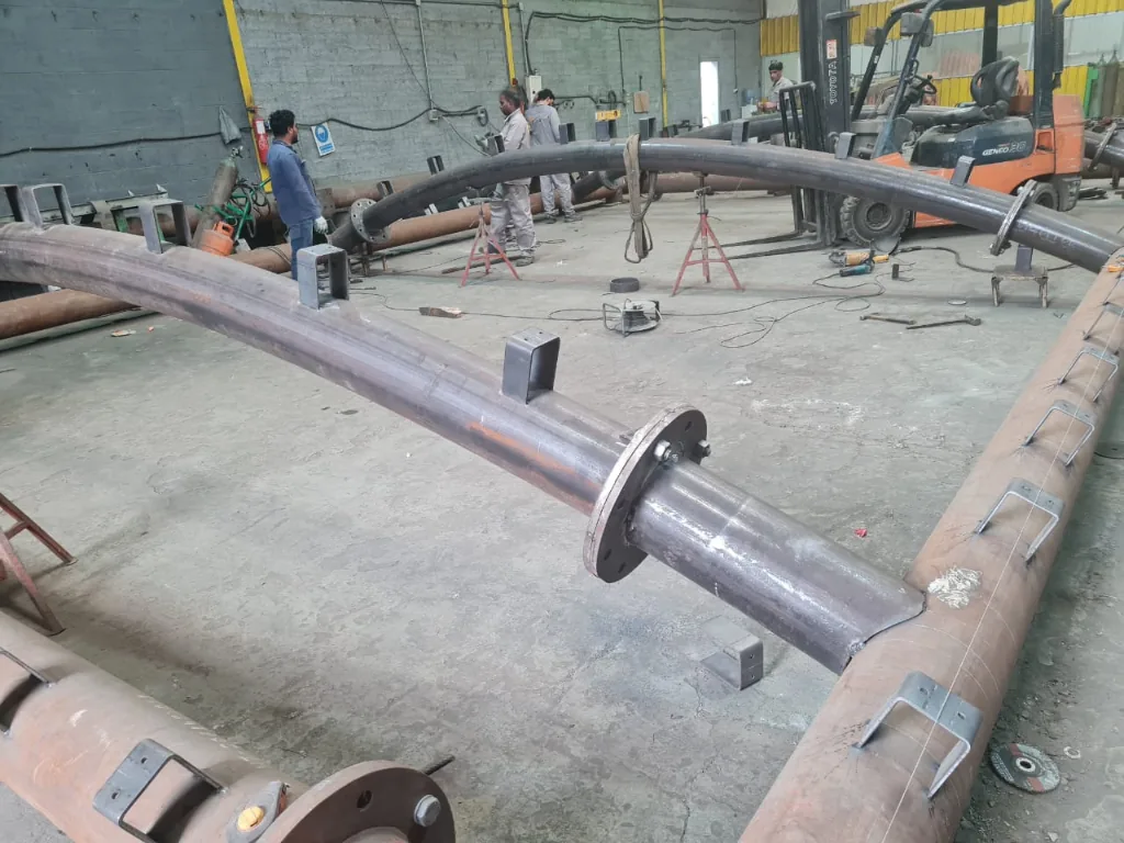
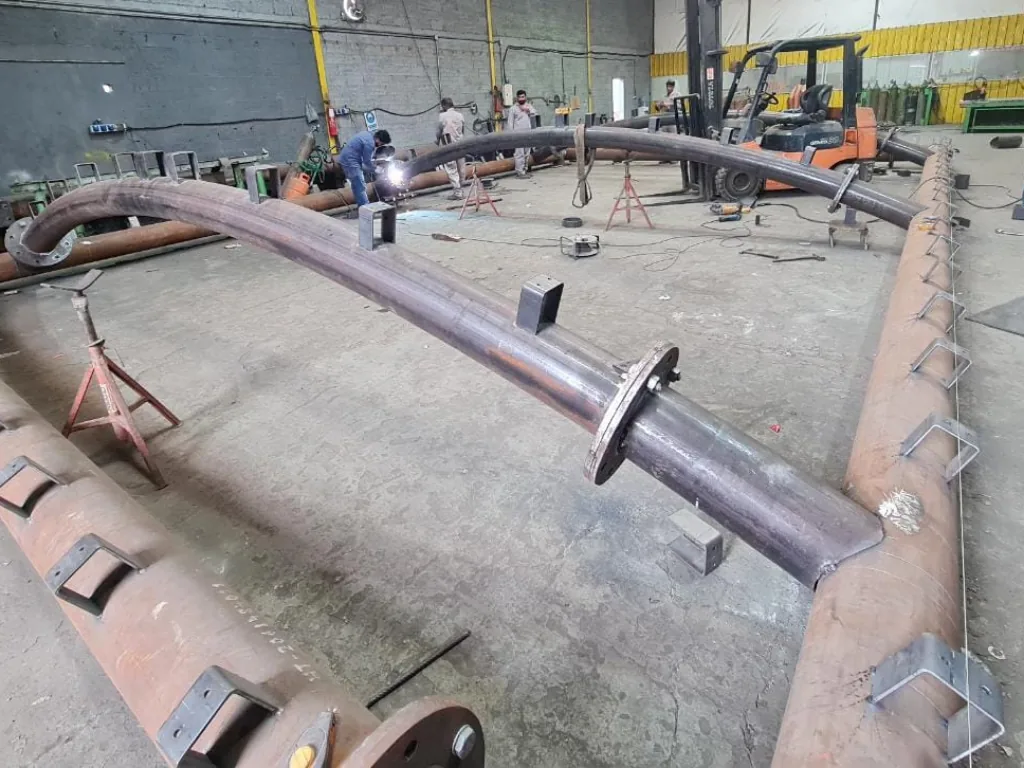
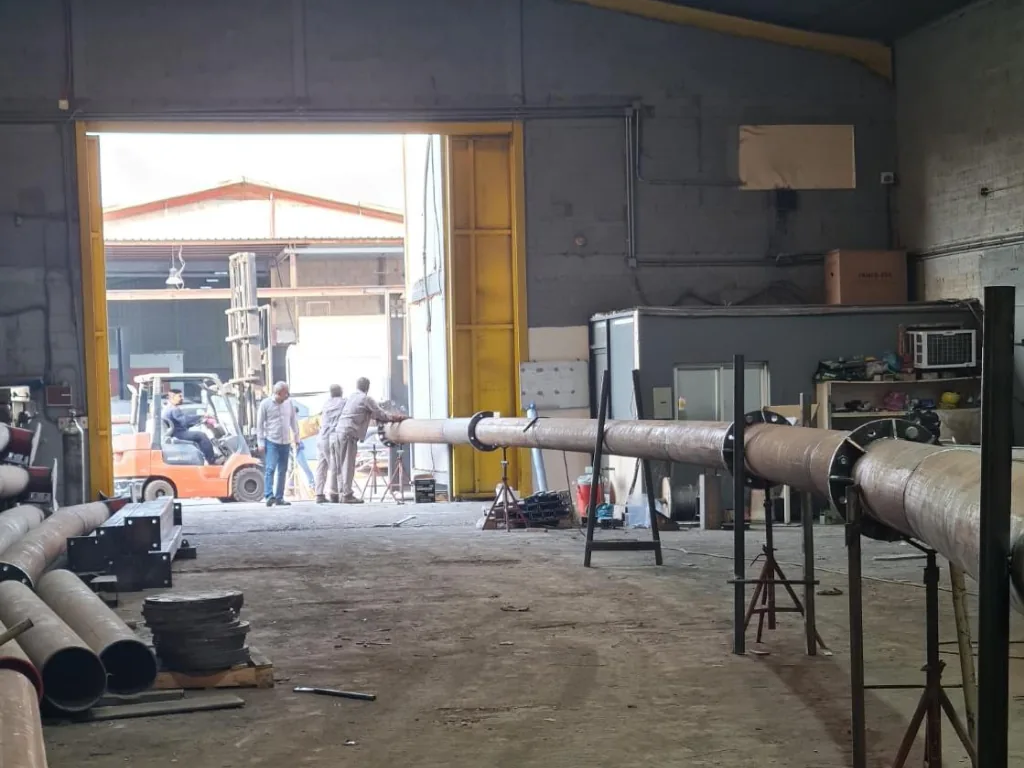
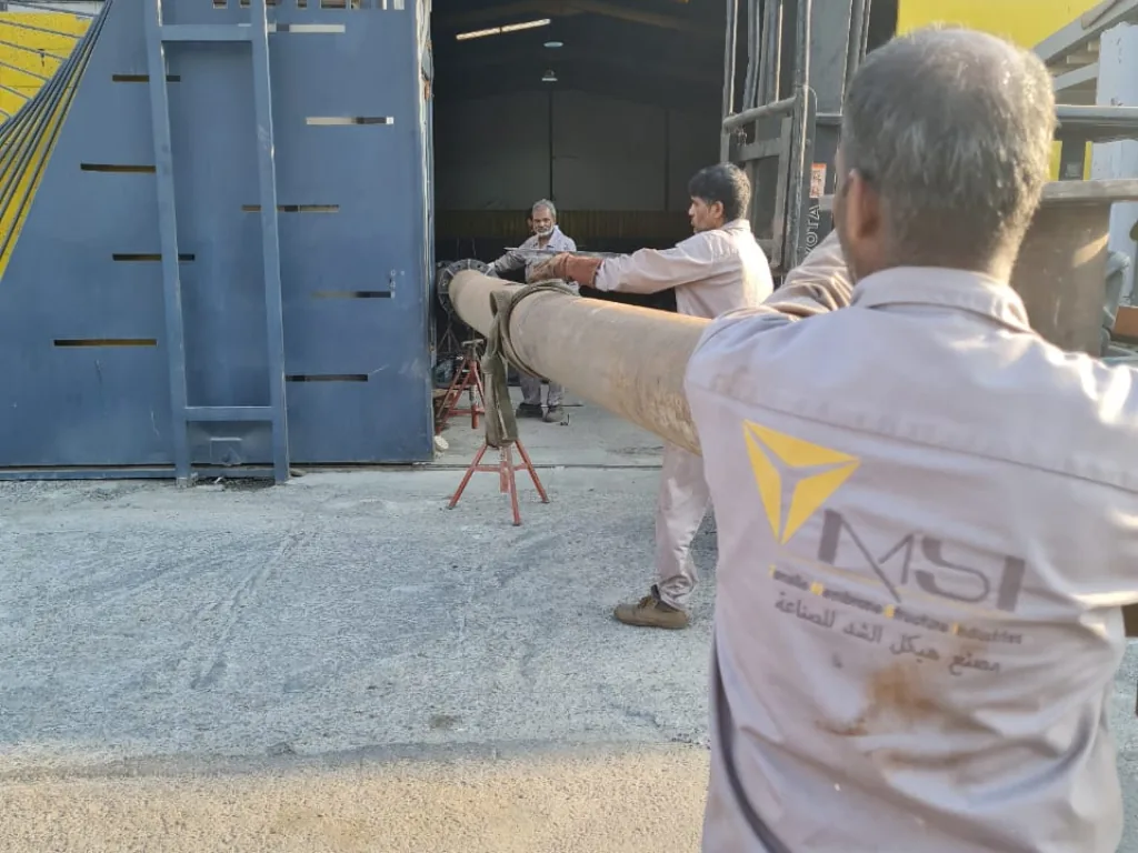
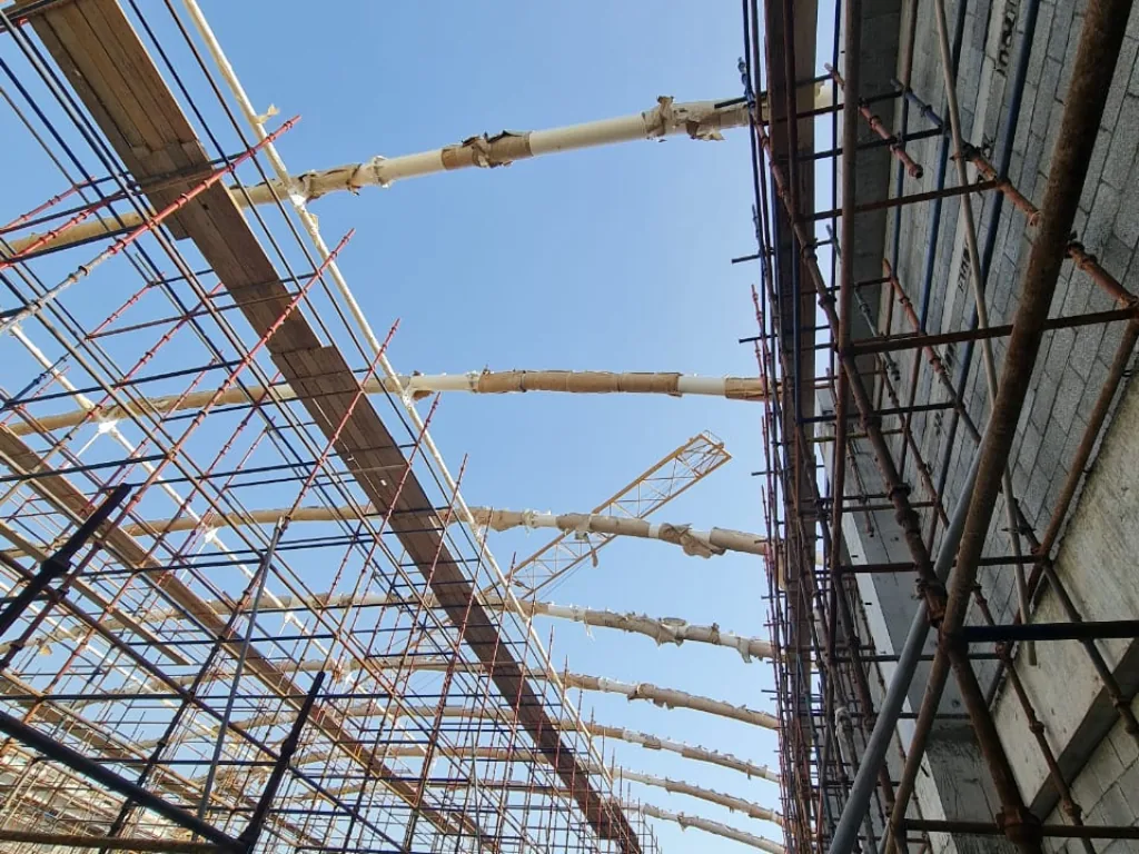
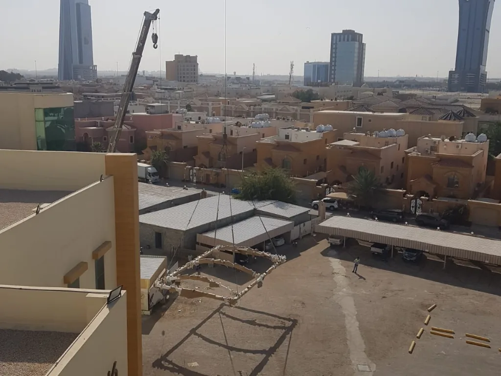
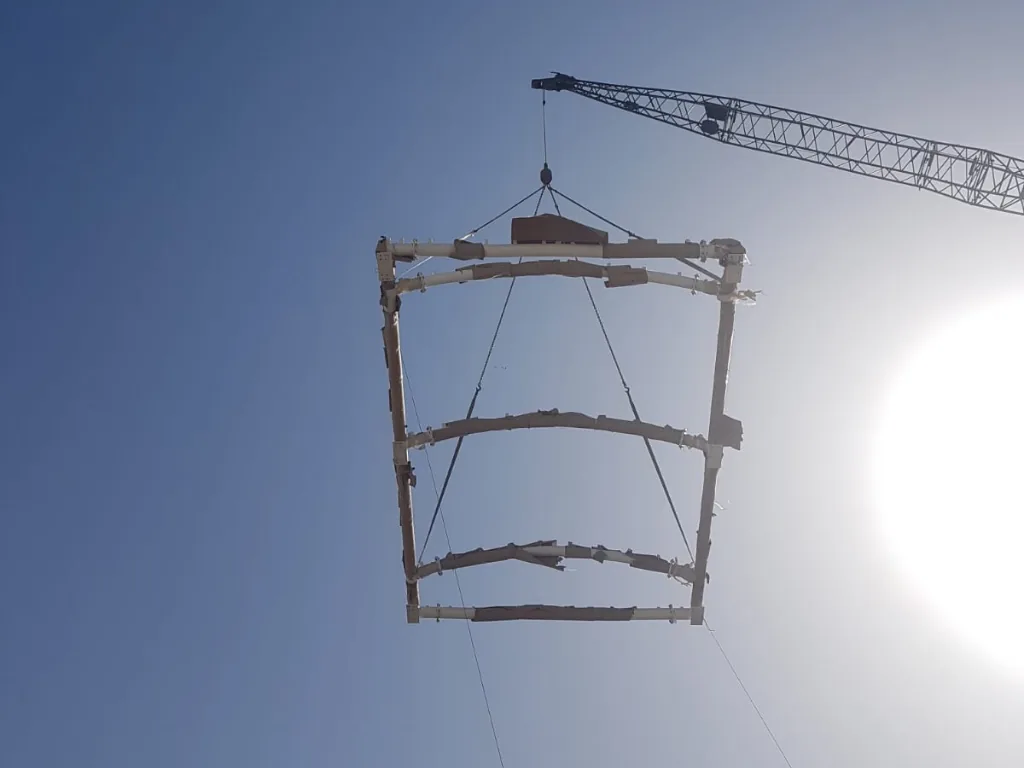
The primary structure is a grid of rolled tubular steel arches, fabricated, trial-assembled and coated in the TMSI factory for the coastal Eastern Province environment, then pre-assembled at ground level and lifted into place. Each ETFE cushion was test-inflated and inspected in the factory before dispatch.
PROJECT 03
| Project | MACHS — Mohammed Al-Mana College for Health Sciences |
|---|---|
| Location | Dammam, Saudi Arabia |
| System | ETFE double layer cushions |
| Approx. area | 1,500+ m2 |
| Cushion pressure | 250 – 300 Pa |
| Inflation | Air handling unit, dual fan |
| Structure | Rolled tubular steel arch grid |
| Scope | Design, supply and install |
Every panel is engineered, patterned and welded in our Dammam factory, then delivered to site as a finished, numbered assembly. The sequence below follows the actual production and installation route used on this project.
DESIGN & ENGINEERING
For the ETFE structures, this pre calculation report has been prepared. The aim of the pre calculation report is to check the conceptional design of structure and load conditions.
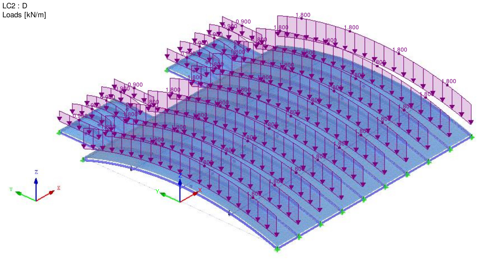
The dead load of the structural elements have been taken into calculation by the software. The collateral load is taken into calculation as 0.4 kN/m² × 4.5 m = 1.8 kN/m.
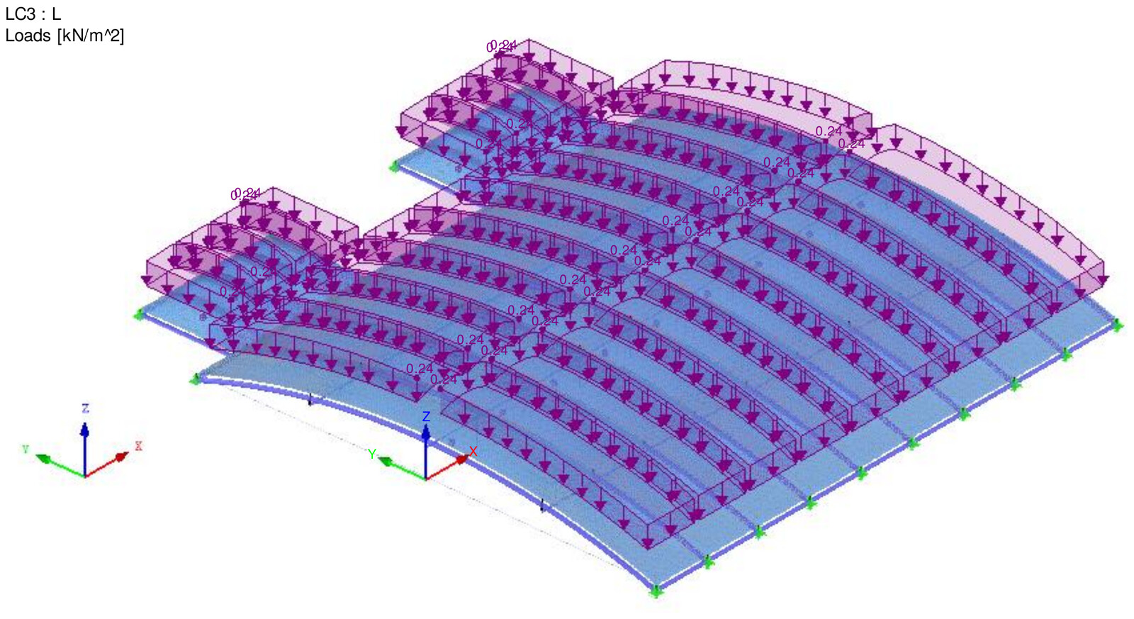
The live load is taken into calculation as 0.24 kN/m² as per ASCE 7-16.
The wind load is taken into calculation as 152 km/h as per SBC 301.
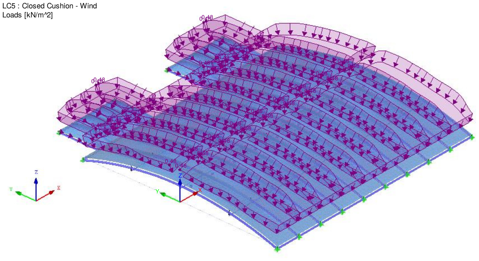
qz = 0.613 KzKztKdKeV² (N/m²); V in m/s (26.10-1.si) · P = qz · G
ASCE 7-16: Minimum Design Loads and Associated Criteria for Buildings and Other Structures.
| Definitions | Symbol | Unit | Value | Formulation |
|---|---|---|---|---|
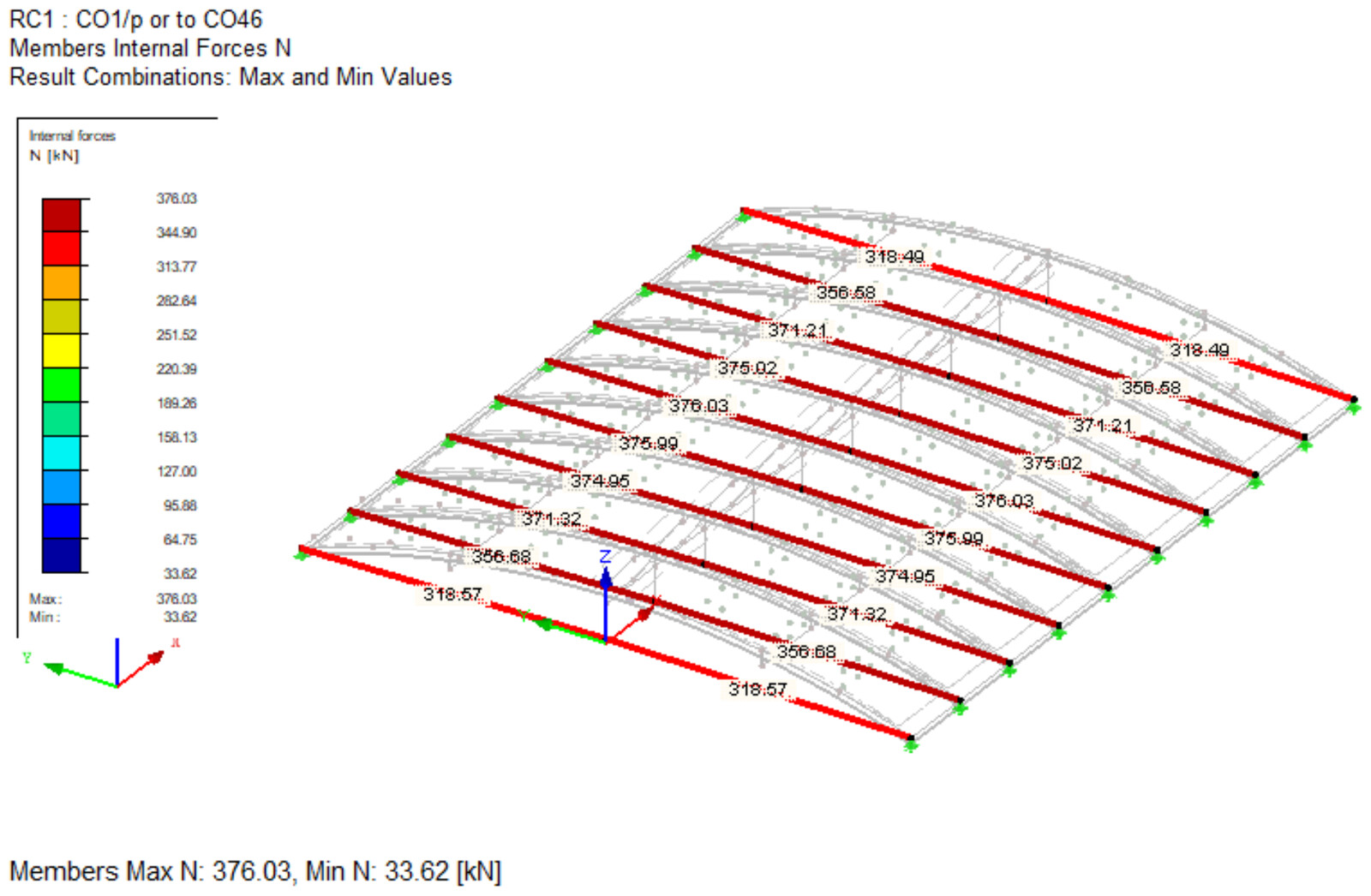
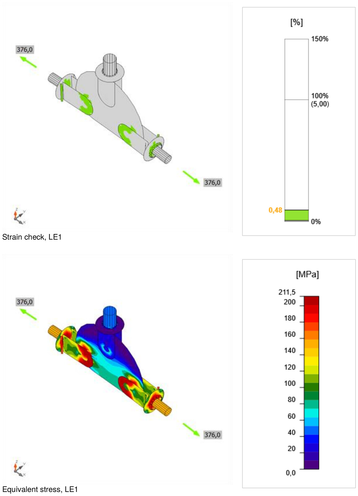
| Cable tension | Nges | [kN] | 376.00 | |
| Quantity of cables | n | [-] | 1 | |
| Cable tension in the single cable | Nseil | [kN] | 376.00 | |
| Design Criteria | LRFD | |||
| Load Safety Factor | γf | [-] | 1.00 | |
| Material Safety Factor | γR | [-] | 1.00 | (usually 1.0) |
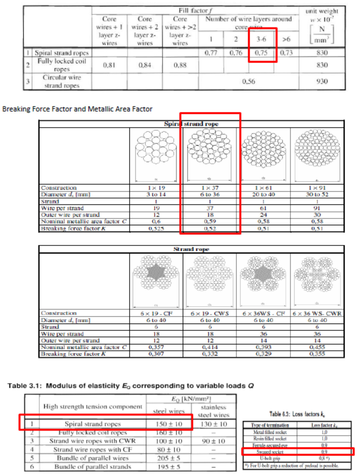
| Cable Type | 1X37 | |||
| Cable Diameter | d | [mm] | 36 | |
| Tensile Strength | Rr | [N/mm²] | 1770 | |
| Youngs Modulus for variable action | EQ | [kN/cm²] | 15000 | |
| Filling load factor | f | [-] | 0.750 | |
| Equavalent Diameter Factor | fed | [-] | 0.866 | |
| Equavalent Diameter (Sap2000) | de | [mm] | 31.18 | =de*fed |
| Reduction dirilling | k | [-] | 0.883 | |
| Self Weight factor | w | [kg/cm²] | 0.830 | |
| Breaking Load Factor | K | [-] | 0.520 | = π*f*k/4 |
| Metallic Cross Sectional Area | Am | [cm²] | 7.634 | |
| Nominal Metallic Areac Factor | C | [-] | 0.590 | |
| Stifness Single Cable | EA | [MN] | 114.511 | |
| Stifness All cables | EAges | [MN] | 114.511 | |
| Cable Weight | g | [kg/m] | 6.34 | =Am*w |
| Minimum Breaking Load Cable | Fmin | [kN] | 894.6 | = K*d2*Rr/1000 |
| Socet Type | Swaged Socket | |||
| Loss factor (Due to cable fitting) | ke | [-] | 0.90 | |
| Characteristic value of the resistance | Fuk | [kN] | 805.2 | =Fmin*ke |
| Design Value of the cable tension | FEd | [kN] | 376.00 | =Nseil*γf |
| Design value of the cable resistance | Frd | [kN] | 536.78 | =Fuk/1.5*γR |
| Verification in the ultimate limit state | Fed/Frd | [-] | 0.70 | OK |
| Name | Cross-section | β – Direction [°] | γ - Pitch [°] | α - Rotation [°] | Offset ex [mm] | Offset ey [mm] | Offset ez [mm] | Forces in |
|---|---|---|---|---|---|---|---|---|
| M1 | 1 - CHS323.9/10.0 | 0,0 | -90,0 | 0,0 | 0 | 0 | 0 | Node |
| Item | Grade | Loads | F t [kN] | V [kN] | φR n,bearing [kN] | Ut t [%] | Ut s [%] | Ut ts [%] | Status |
|---|---|---|---|---|---|---|---|---|---|
| B1 | M24 8.8 - 1 | LE7 | 22,8 | 46,8 | 311,0 | 11,2 | 38,4 | - | OK |
| B2 | M24 8.8 - 1 | LE8 | 40,3 | 46,5 | 311,0 | 19,8 | 38,1 | - | OK |
| B3 | M24 8.8 - 1 | LE8 | 20,0 | 47,0 | 311,0 | 9,8 | 38,6 | - | OK |
| B4 | M24 8.8 - 1 | LE8 | 0,2 | 47,3 | 311,0 | 0,1 | 38,8 | - | OK |
| B5 | M24 8.8 - 1 | LE8 | 0,6 | 47,7 | 311,0 | 0,3 | 39,0 | - | OK |
| B6 | M24 8.8 - 1 | LE8 | 0,2 | 47,7 | 311,0 | 0,1 | 39,1 | - | OK |
| B7 | M24 8.8 - 1 | LE11 | 0,0 | 50,0 | 311,0 | 0,0 | 41,0 | - | OK |
| B8 | M24 8.8 - 1 | LE11 | 23,7 | 49,9 | 311,0 | 11,6 | 40,9 | - | OK |
| Grade | φR n,tension [kN] | φR n,shear [kN] |
|---|---|---|
| M24 8.8 - 1 | 203,4 | 122,0 |
| Item | Edge | Xu | T h [mm] | L s [mm] | L [mm] | L c [mm] | Loads | F n [kN] | φR n [kN] | Ut [%] | Status |
|---|---|---|---|---|---|---|---|---|---|---|---|
| PP1a | RIB1a | E70xx | 4,0 | 5,7 | 74 | 9 | LE8 | 5,7 | 11,6 | 49,2 | OK |
| E70xx | 4,0 | 5,7 | 74 | 9 | LE11 | 6,4 | 11,5 | 55,2 | OK | ||
| B1-arc 5 | RIB1a | E70xx | 4,0 | 5,7 | 155 | 10 | LE11 | 4,0 | 9,2 | 43,6 | OK |
| E70xx | 4,0 | 5,7 | 155 | 10 | LE8 | 4,3 | 9,1 | 47,0 | OK | ||
| PP1a | RIB1b | E70xx | 4,0 | 5,7 | 74 | 9 | LE10 | 6,2 | 11,7 | 53,1 | OK |
| E70xx | 4,0 | 5,7 | 74 | 9 | LE10 | 6,5 | 11,3 | 57,6 | OK | ||
| B1-arc 13 | RIB1b | E70xx | 4,0 | 5,7 | 155 | 10 | LE10 | 4,4 | 9,3 | 47,3 | OK |
| E70xx | 4,0 | 5,7 | 155 | 10 | LE10 | 4,7 | 9,2 | 51,0 | OK | ||
| PP1a | RIB1c | E70xx | 4,0 | 5,7 | 74 | 9 | LE1 | 6,5 | 11,5 | 56,7 | OK |
| E70xx | 4,0 | 5,7 | 74 | 9 | LE1 | 6,2 | 11,8 | 52,3 | OK | ||
| B1-arc 21 | RIB1c | E70xx | 4,0 | 5,7 | 155 | 10 | LE1 | 4,4 | 9,4 | 46,7 | OK |
| E70xx | 4,0 | 5,7 | 155 | 10 | LE1 | 4,8 | 9,2 | 51,8 | OK | ||
| PP1a | RIB1d | E70xx | 4,0 | 5,7 | 74 | 9 | LE12 | 5,7 | 11,5 | 49,3 | OK |
| E70xx | 4,0 | 5,7 | 74 | 9 | LE4 | 4,2 | 10,9 | 39,0 | OK | ||
| B1-arc 29 | RIB1d | E70xx | 4,0 | 5,7 | 155 | 10 | LE12 | 3,4 | 9,3 | 36,2 | OK |
| E70xx | 4,0 | 5,7 | 155 | 10 | LE12 | 3,9 | 9,1 | 42,8 | OK | ||
| PP1a | RIB1e | E70xx | 4,0 | 5,7 | 74 | 9 | LE12 | 4,7 | 10,6 | 44,1 | OK |
| E70xx | 4,0 | 5,7 | 75 | 9 | LE8 | 5,2 | 12,1 | 43,0 | OK | ||
| B1-arc 37 | RIB1e | E70xx | 4,0 | 5,7 | 155 | 10 | LE8 | 4,2 | 9,3 | 45,6 | OK |
| E70xx | 4,0 | 5,7 | 155 | 10 | LE11 | 4,7 | 9,1 | 51,9 | OK | ||
| PP1a | RIB1f | E70xx | 4,0 | 5,7 | 75 | 11 | LE10 | 7,5 | 13,6 | 55,5 | OK |
| E70xx | 4,0 | 5,7 | 75 | 11 | LE10 | 7,5 | 13,5 | 55,4 | OK | ||
| B1-arc 44 | RIB1f | E70xx | 4,0 | 5,7 | 155 | 10 | LE10 | 5,6 | 9,5 | 59,1 | OK |
| E70xx | 4,0 | 5,7 | 155 | 10 | LE10 | 5,0 | 9,9 | 50,4 | OK | ||
| PP1a | RIB1g | E70xx | 4,0 | 5,7 | 75 | 11 | LE1 | 7,6 | 13,5 | 56,5 | OK |
| E70xx | 4,0 | 5,7 | 75 | 11 | LE1 | 7,7 | 13,6 | 56,7 | OK | ||
| B1-arc 53 | RIB1g | E70xx | 4,0 | 5,7 | 155 | 10 | LE1 | 5,0 | 9,9 | 50,6 | OK |
| E70xx | 4,0 | 5,7 | 155 | 10 | LE1 | 5,6 | 9,5 | 59,3 | OK | ||
| PP1a | RIB1h | E70xx | 4,0 | 5,7 | 74 | 11 | LE8 | 4,5 | 13,5 | 33,6 | OK |
| E70xx | 4,0 | 5,7 | 74 | 11 | LE11 | 6,3 | 13,4 | 46,8 | OK | ||
| B1-arc 60 | RIB1h | E70xx | 4,0 | 5,7 | 155 | 10 | LE12 | 4,4 | 9,1 | 48,3 | OK |
| E70xx | 4,0 | 5,7 | 155 | 10 | LE12 | 3,6 | 9,5 | 38,3 | OK |
Send us the area, the city and the fabric you need — we come back with a system and an indicative budget.