Al Jubail Project

ETFE printed single layer

Area256 m²
FabricETFE
CityAl Jubail
SectorCommercial

Project overview

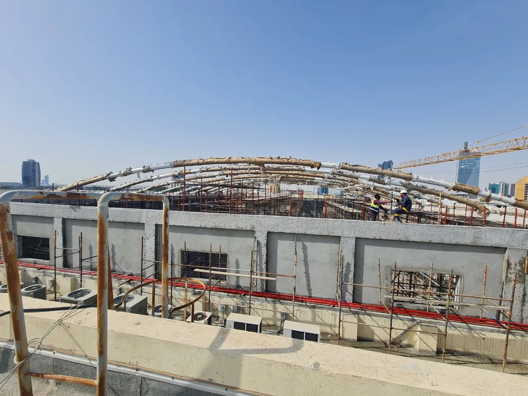
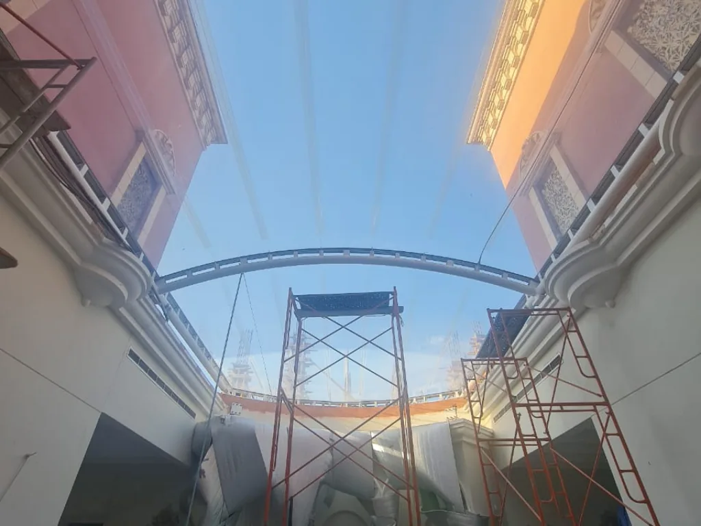
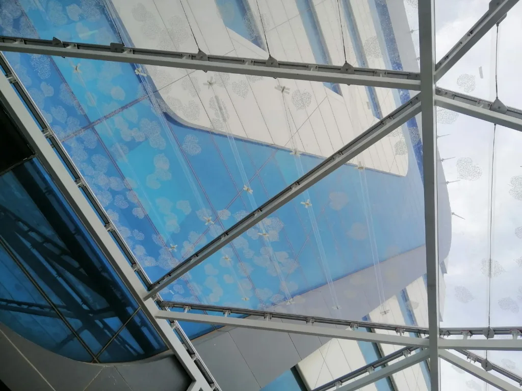
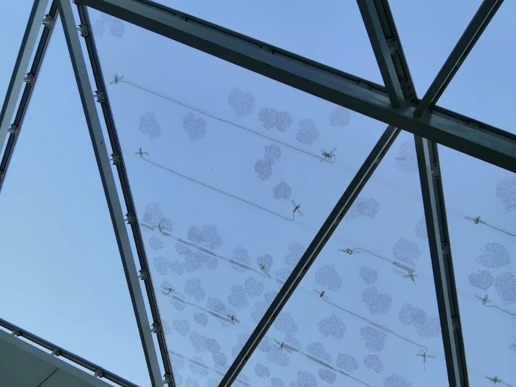
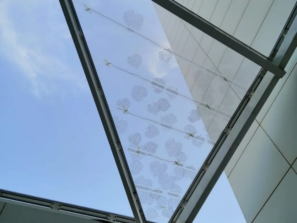
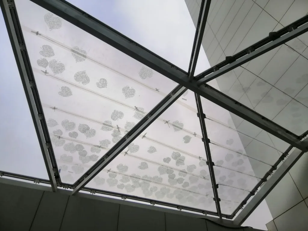
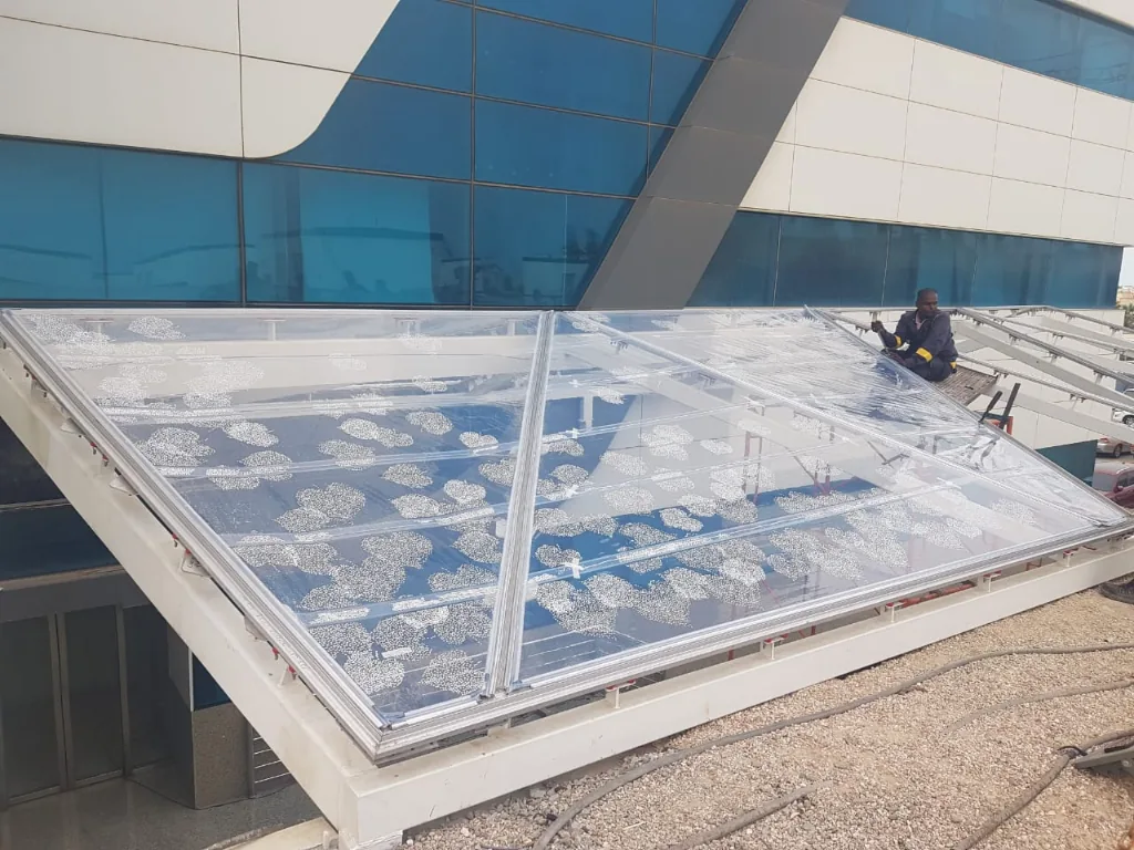
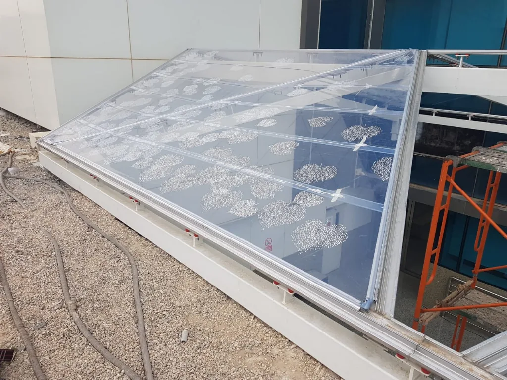
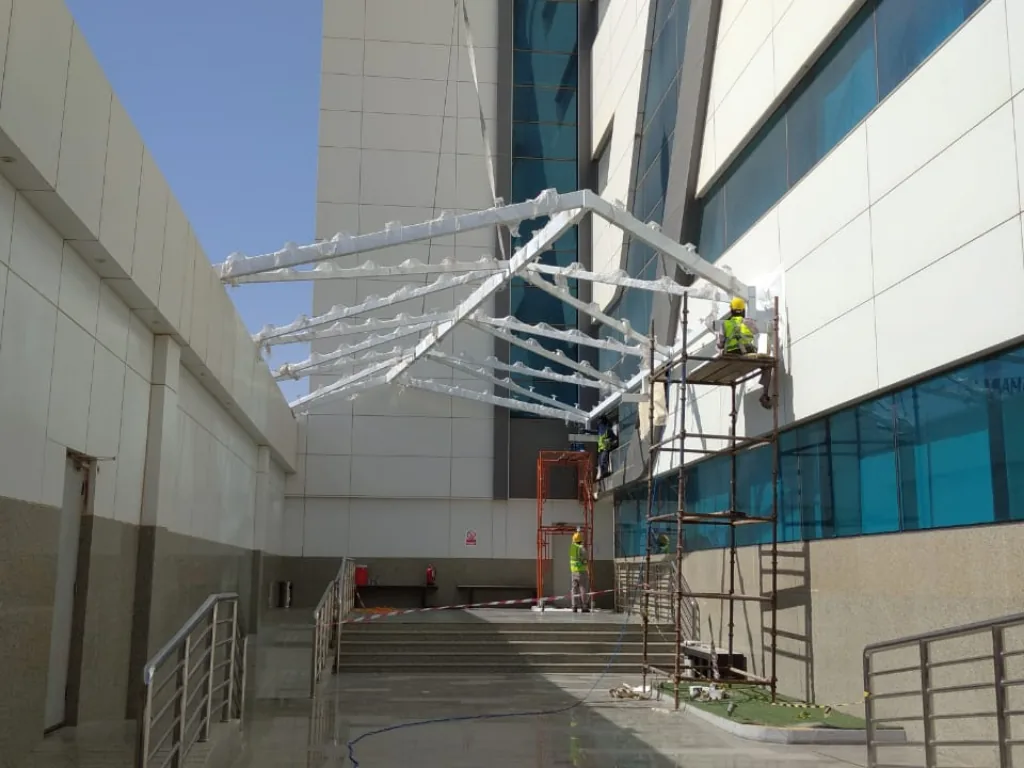
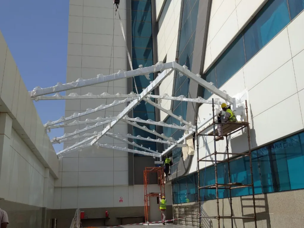
The Al Jubail project is a printed single-layer ETFE roof of more than 256 m², set between existing façades in Al Jubail. TMSI's scope was design, supply and installation.

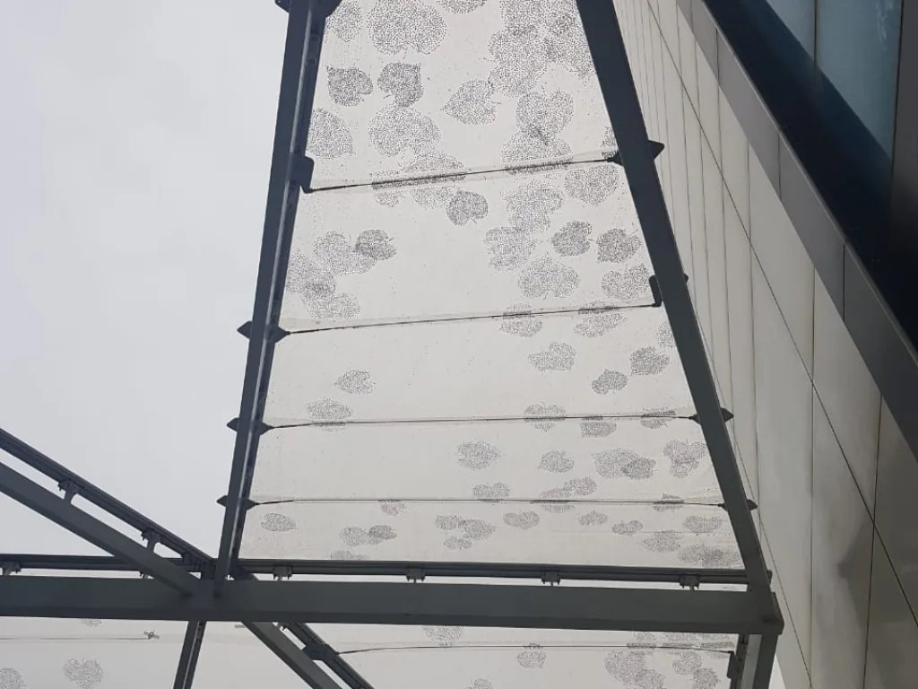
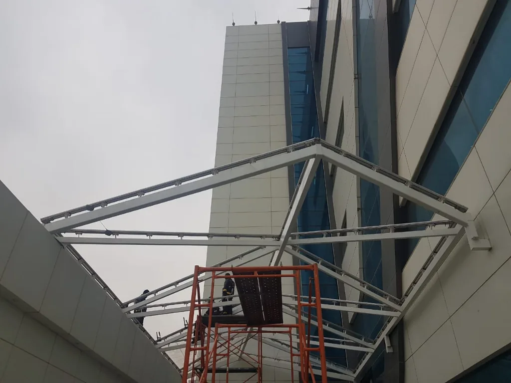
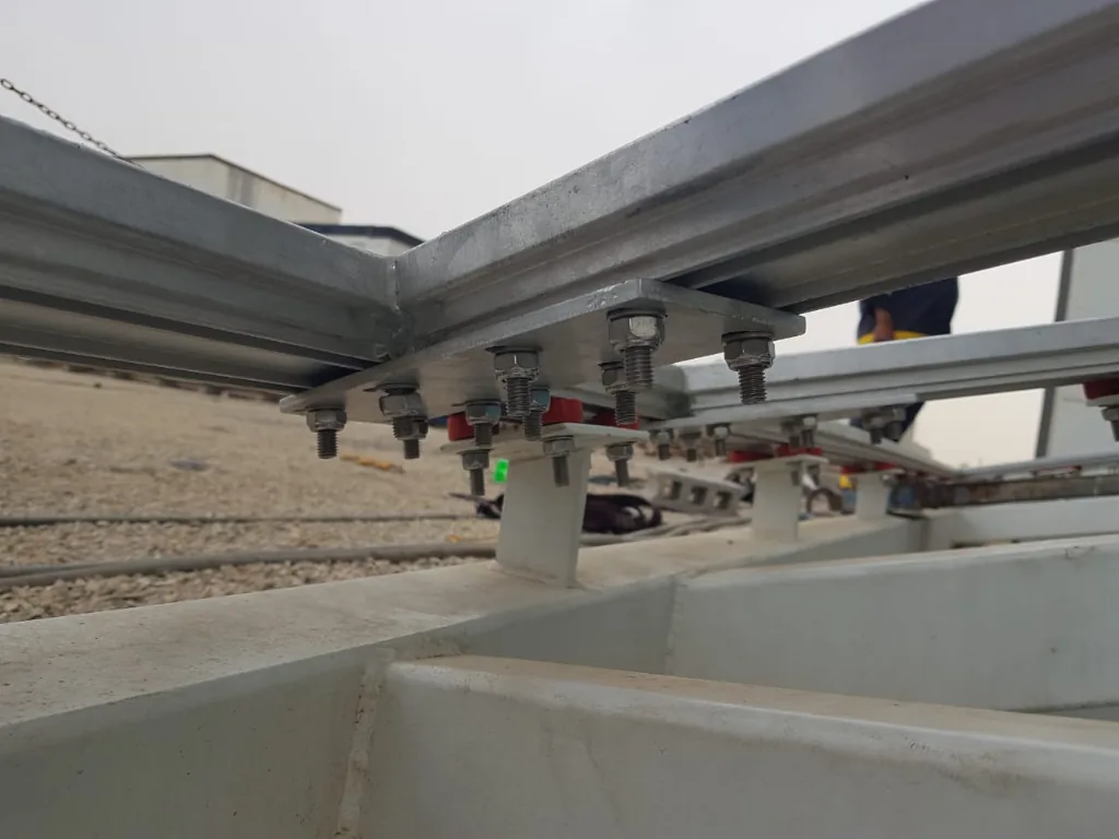
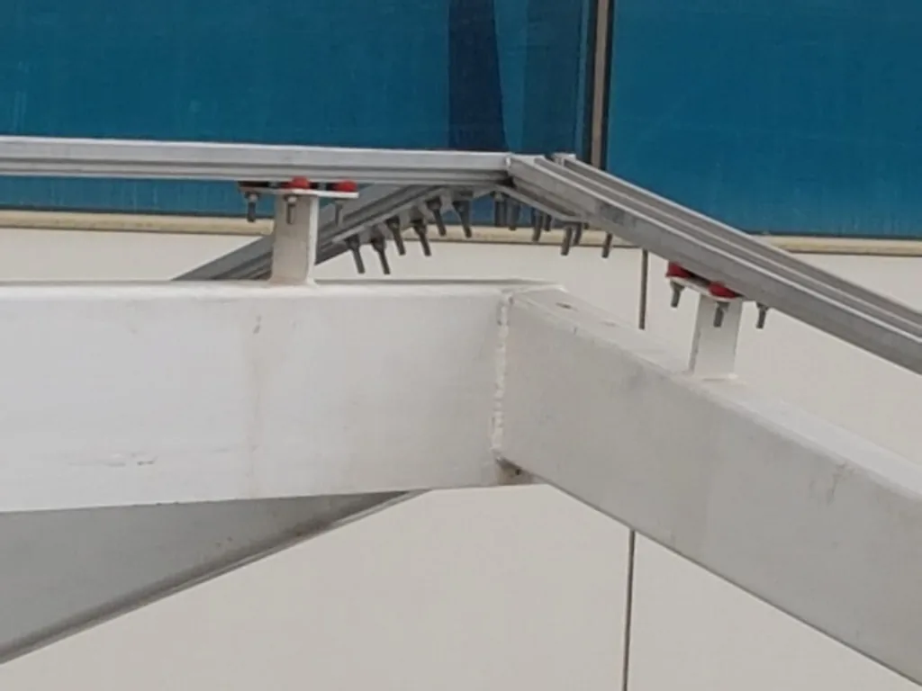
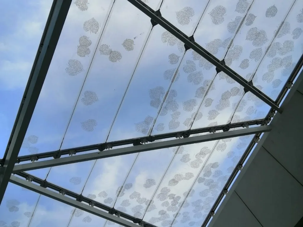
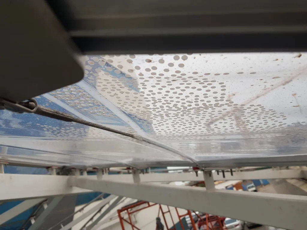
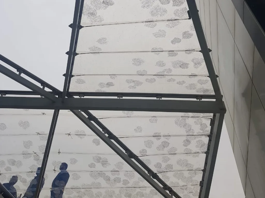
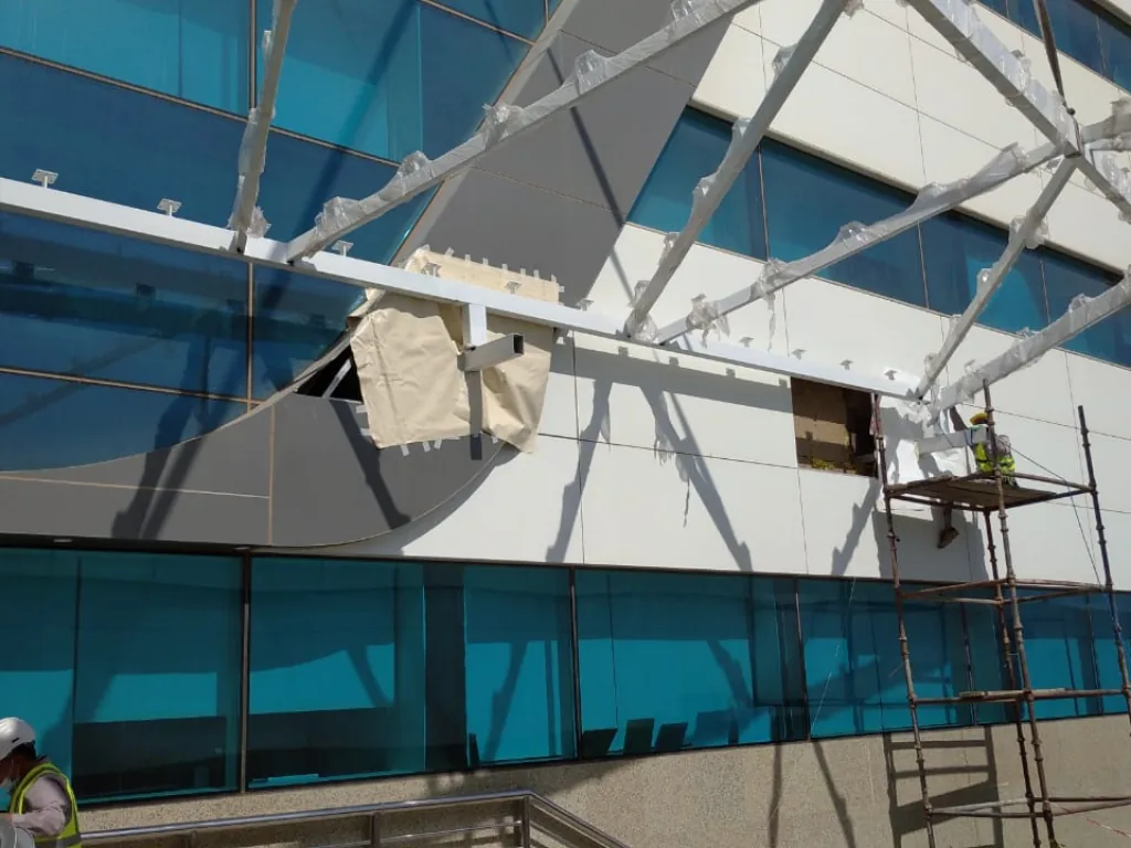
The roof is made of free-form, non-planar trapezoidal panels on steel frames, each set to a pitch that allows rainwater to drain freely. The ETFE foil carries a custom silver frit printed on its outer surface; the frit coverage was tuned to reduce solar gain and glare while keeping the roof visibly translucent, and a printed sample was issued for approval before production. Stainless steel cables restrain the membrane, and an aluminium perimeter extrusion clamps the foil and forms the water seal.

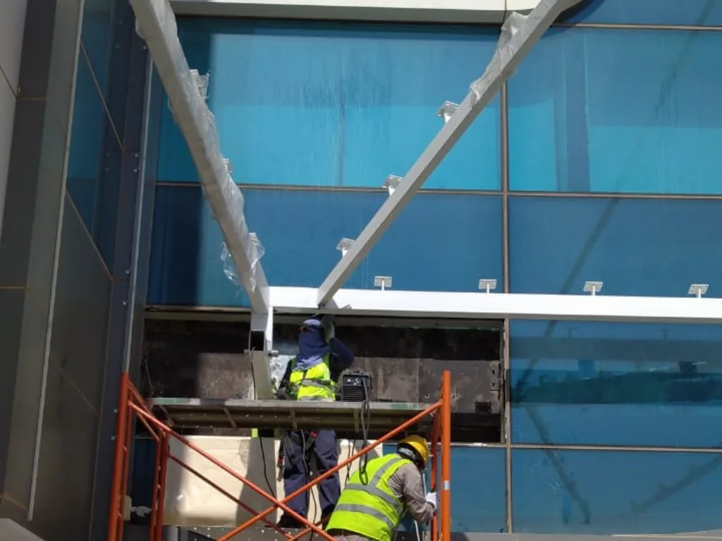
A single-layer ETFE system needs no air supply or power. Panels were patterned, cut and thermally welded in the Dammam factory, assembled to their frames at low level where possible and lifted into position, then tensioned, sealed and water-tested against the surrounding façade before handover.

PROJECT 02

ETFE Printed Single Layer · Al Jubail, Saudi Arabia

Project data

Project data
ProjectAl Jubail Project
LocationAl Jubail, Saudi Arabia
SystemETFE single layer, printed
Approx. area256+ m2
Foil finishSilver frit, custom pattern
RestraintStainless steel cables
StructureTrapezoidal steel frames
ScopeDesign, supply and install

Scope of works

  • Design of non-planar trapezoidal skylight panels between existing façades
  • Fabrication of the supporting steel frame and aluminium extrusion system
  • Custom frit printing, patterning and welding of the ETFE foil
  • Panel pre-assembly at ground level and lifting into position
  • Installation, tensioning, sealing and commissioning

System description

  1. 01Single skin ETFE welded membrane with a custom silver frit printed on the outer surface.
  2. 02Frit coverage tuned to reduce solar gain and glare while retaining visual translucency.
  3. 03Free-form, non-planar trapezoidal panels set to an adequate pitch for self-drainage.
  4. 04Fully integrated aluminium perimeter clamping and water sealant system.
  5. 05Fully integrated aluminium perimeter clamping and water sealant system.

Al Jubail Project — Fabrication & Installation

Every panel is engineered, patterned and welded in our Dammam factory, then delivered to site as a finished, numbered assembly. The sequence below follows the actual production and installation route used on this project.

  1. 01 Survey & Form FindingThe opening between the existing façades is surveyed and the trapezoidal panel geometry generated, with pitch set to guarantee free drainage.
  2. 02 Print Design & ApprovalFrit pattern and coverage percentage are developed against the light transmission and glare targets, then issued as a printed sample for approval.
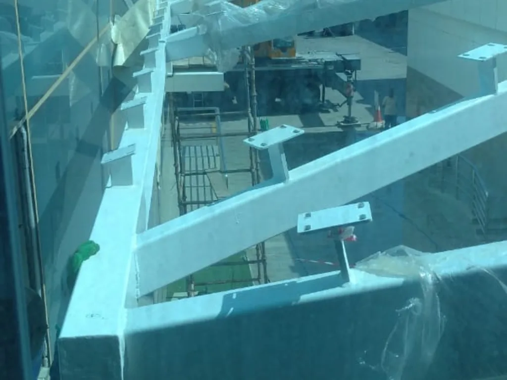
  3. 03 Steel FabricationFrames are fabricated, coated and erected, then surveyed in position before the aluminium extrusion line is set out.
  4. 04 Extrusion InstallationThe perimeter extrusion and clamping profile are fixed to the steel, aligned and levelled to form a continuous, sealed clamping line.
  5. 05 Clamping Detail & SealantBase extrusion, gaskets and sealant are installed so that the membrane clamp also forms the primary weather line of the assembly.
  6. 06 Panel FabricationPrinted foil is patterned, cut and thermally welded into finished panels with keder edges, then folded and packed to the installation sequence.
  7. 07 Assembly & LiftingPanels are assembled to their frames at low level where possible and lifted into place, minimising handling and exposure at height.
  8. 08 TensioningThe keder is fed into the extrusion, cables are tensioned to the design pre-stress and clamping plates are torqued in a controlled sequence.
  9. 09 Sealing & Water TestPerimeter flashings and seals are completed and the assembly is water-tested against the surrounding façade before sign-off.
  10. 10 Inspection & HandoverPrint alignment, tension and drainage are verified. Cleaning, as-built drawings and the maintenance manual complete the handover.

DESIGN & ENGINEERING

Al Jubail Project – Design & Engineering

Brief Description of Structure — Roof Geometry & Support Conditions

The geometry of the project can be considered as a gable roof, which is anchored on one of the long sides on a reinforced concrete wall 250 mm thick and with a concrete strength of f’c = 4,000 psi (280 kg/cm²); And on the other long side it supported on some cantilever beams that will be anchored to the reinforced concrete beams of 300 mm x 600 mm (width and depth) of the existing building, which have a concrete strength of f’c = 4,000 psi (280 kg/cm²).
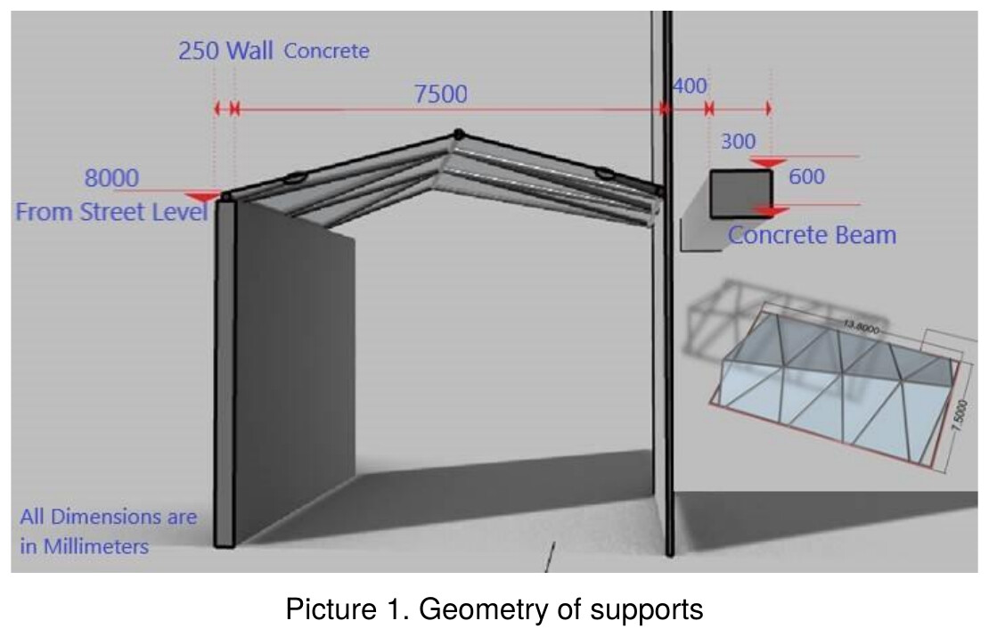
Sketch of the support conditions: the 250 mm concrete wall on one side at 8000 mm from street level, and the 300 × 600 mm concrete beam on the other.
Picture 1. Geometry of supports

ETFE Membrane Stress Analysis — Longitudinal Direction

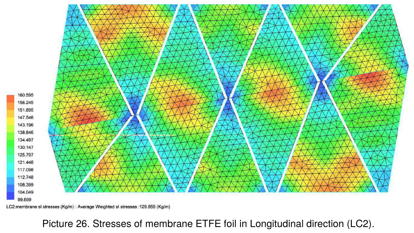
Finite element stress plot of the ETFE foil in the longitudinal direction, triangular mesh coloured by stress with the value scale at the left.
Picture 26. Stresses of membrane ETFE foil in Longitudinal direction (LC2)

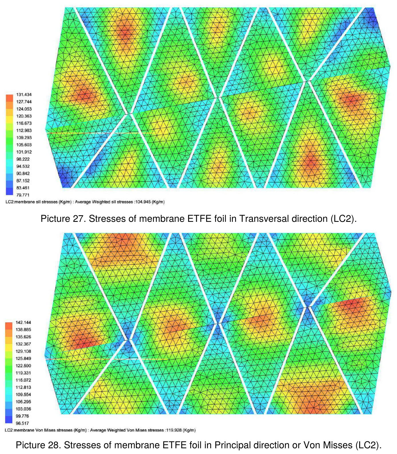
ETFE Membrane Stress Analysis — Transversal & Principal Directions

Two finite element stress plots of the ETFE foil, one in the transversal direction and one in the principal (Von Mises) direction.
Pictures 27–28. Stresses in Transversal direction and in Principal direction / Von Misses (LC2)

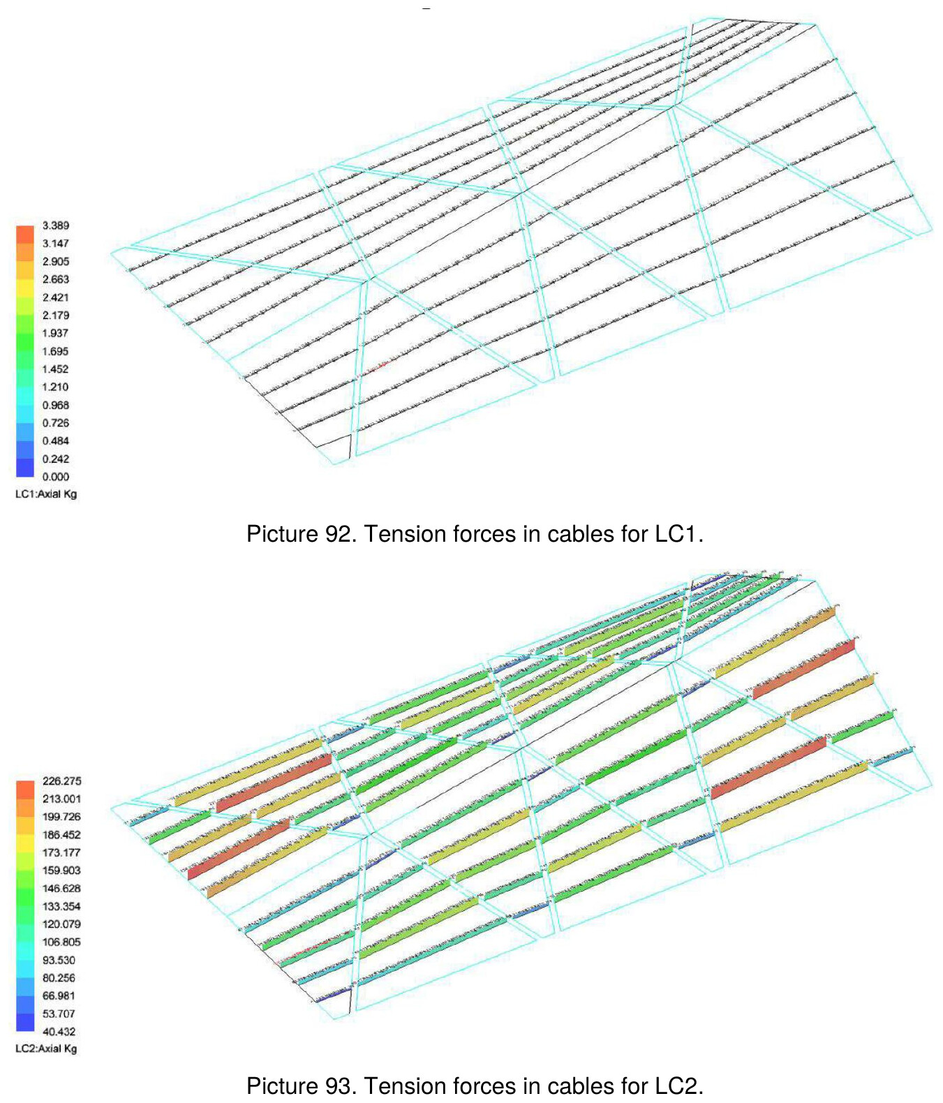
Cable Stress Diagrams — Tension Forces, Load Cases LC1 & LC2

Two axial force diagrams of the cable net, one for load case LC1 and one for LC2, each with its colour scale in kg.
Pictures 92–93. Tension forces in cables for LC1 and LC2

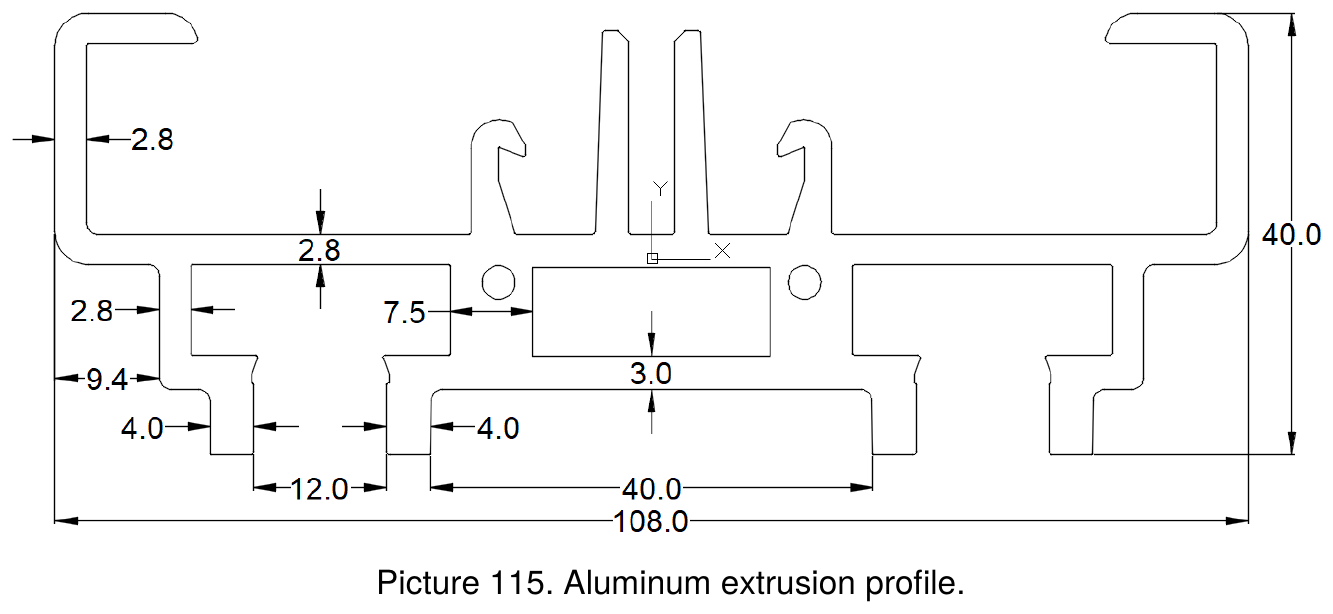
Aluminum Extrusion Profile — Geometry & Section Properties

Dimensioned cross-section of the aluminium extrusion profile, overall width 108.0 mm and height 40.0 mm.
Picture 115. Aluminum extrusion profile
Section properties — 7 rows
Section properties
PropertiesValueUnit
Iyy1'029,236.9mm4
Ixx107,713.4mm4
Area1,080.06mm2
ry=30.87mm
rx=9.99mm
Sy=19,060.5mm3
Sx=4,837.2mm3

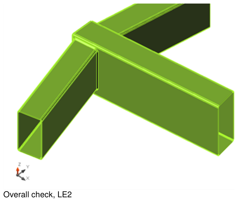
Steel Connection Design Check — Plate & Weld Capacity Summary

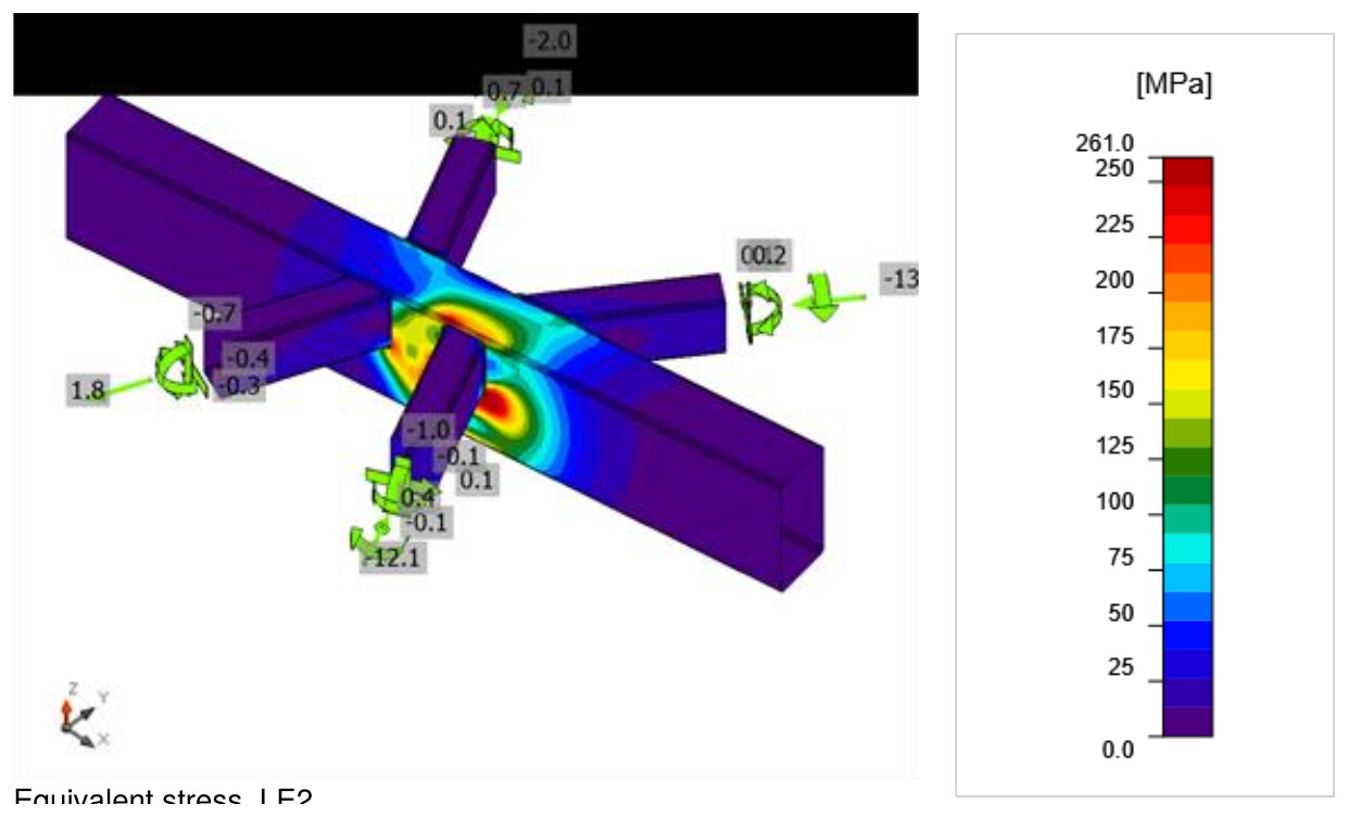
Three-dimensional model of the welded steel connection between the hollow sections, shown in the overall check for load effect LE2.
Overall check, LE2
Summary — 5 rows
Summary
NameValueCheck status
Analysis100.0%OK
Plates0.1 < 5%OK
Welds89.0 < 100%OK
BucklingNot calculated
GMNACalculated
Plates — 5 rows
Plates
NameMaterialFy [MPa]Thickness [mm]LoadsσEd [MPa]εPl [%]Check status
M1A500, Gr. B290.04.4LE2261.30.1OK
M2A500, Gr. B290.04.4LE2261.20.1OK
M3A500, Gr. B290.04.4LE2248.30.1OK
STIFF1A36248.26.4LE2223.40.0OK
SP1A36248.24.8LE2154.30.0OK
Design data — 2 rows
Design data
Materialfy [MPa]εlim [%]
A500, Gr. B290.05.0
A36248.25.0

Steel Connection — Equivalent Stress & Weld Resistance Check

Equivalent stress plot on the connection for load effect LE2, peak stress at the weld shown against a 0 to 261 MPa colour scale.
Equivalent stress, LE2
Welds — 4 rows
Welds
ItemEdgeXuTh [mm]Ls [mm]L [mm]Lc [mm]Fn [kN]φRn [kN]Ut [%]Status
M1-w 2M2E70xx2.13.034941.72.180.9OK
M1-w 4M3E70xx2.13.030441.72.084.2OK
M1-w 2M4E70xx2.13.031841.72.276.7OK
M1-w 2M5E70xx2.13.030541.52.076.3OK

Detailed Result for M1-w 4 / M3 — Weld Resistance Check (AISC 360-16: J2-4)

φRn = φ · Fnw · Awe = 2.0 kN  ≥  Fn = 1.7 kN

Fnw = 360.7 MPa – nominal stress of weld material; FEXX = 482.6 MPa – electrode classification number, i.e. minimum specified tensile strength; θ = 38.5° – angle of loading measured from the weld longitudinal axis; Awe = 7 mm² – effective area of weld critical element.

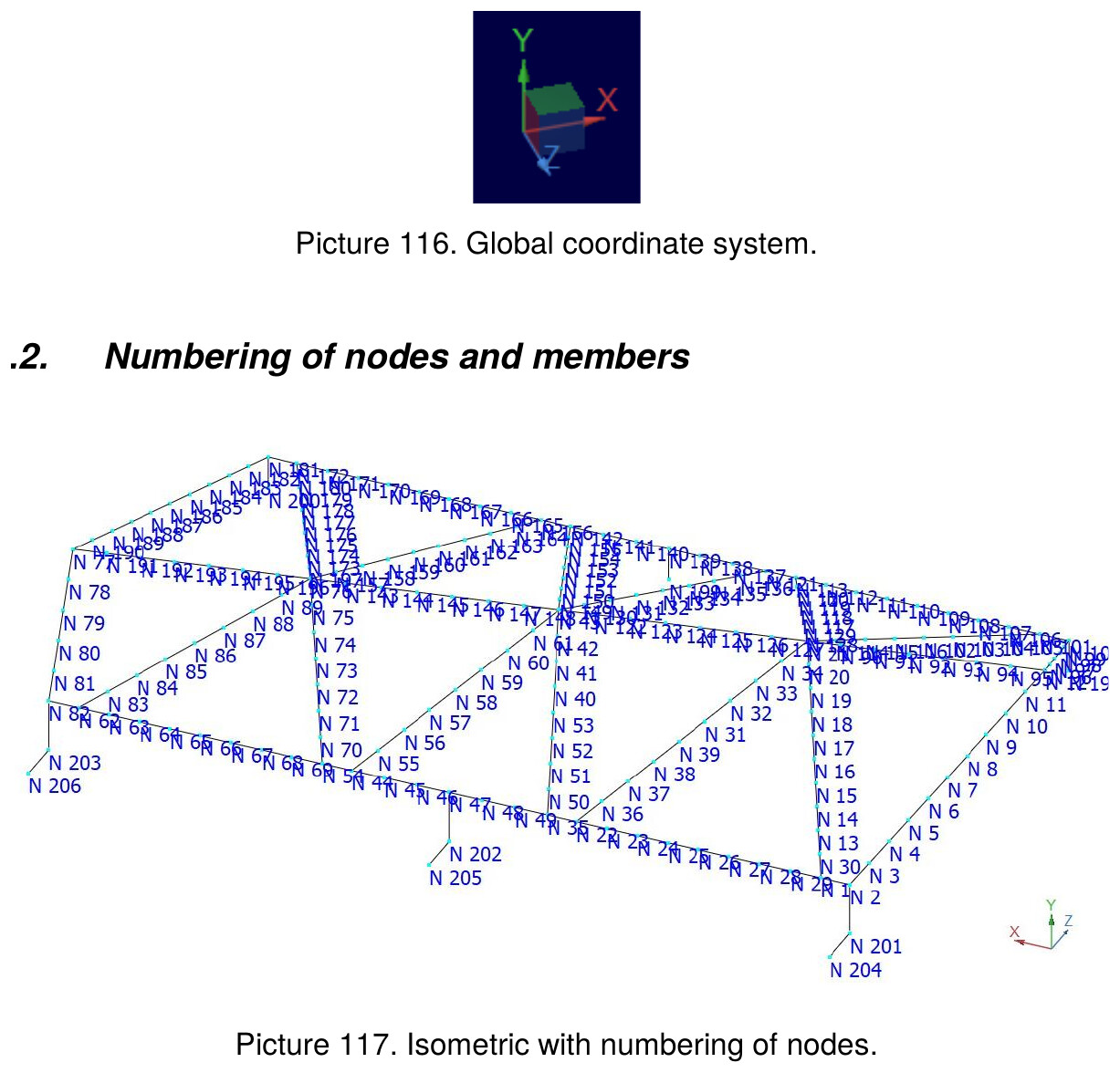
Reaction Report — Global Coordinate System & Node Numbering

Reaction forces are presented as moments and concentrated loads. Each column support has three forces and three moments, one for each axis for recessed supports, and only three forces per axis for articulated supports.

The forces shown here are per node, and are entered according to the global coordinate system as shown.

Global coordinate system and an isometric view of the frame with every node numbered N1 upwards.
Pictures 116–117. Global coordinate system, and isometric with numbering of nodes

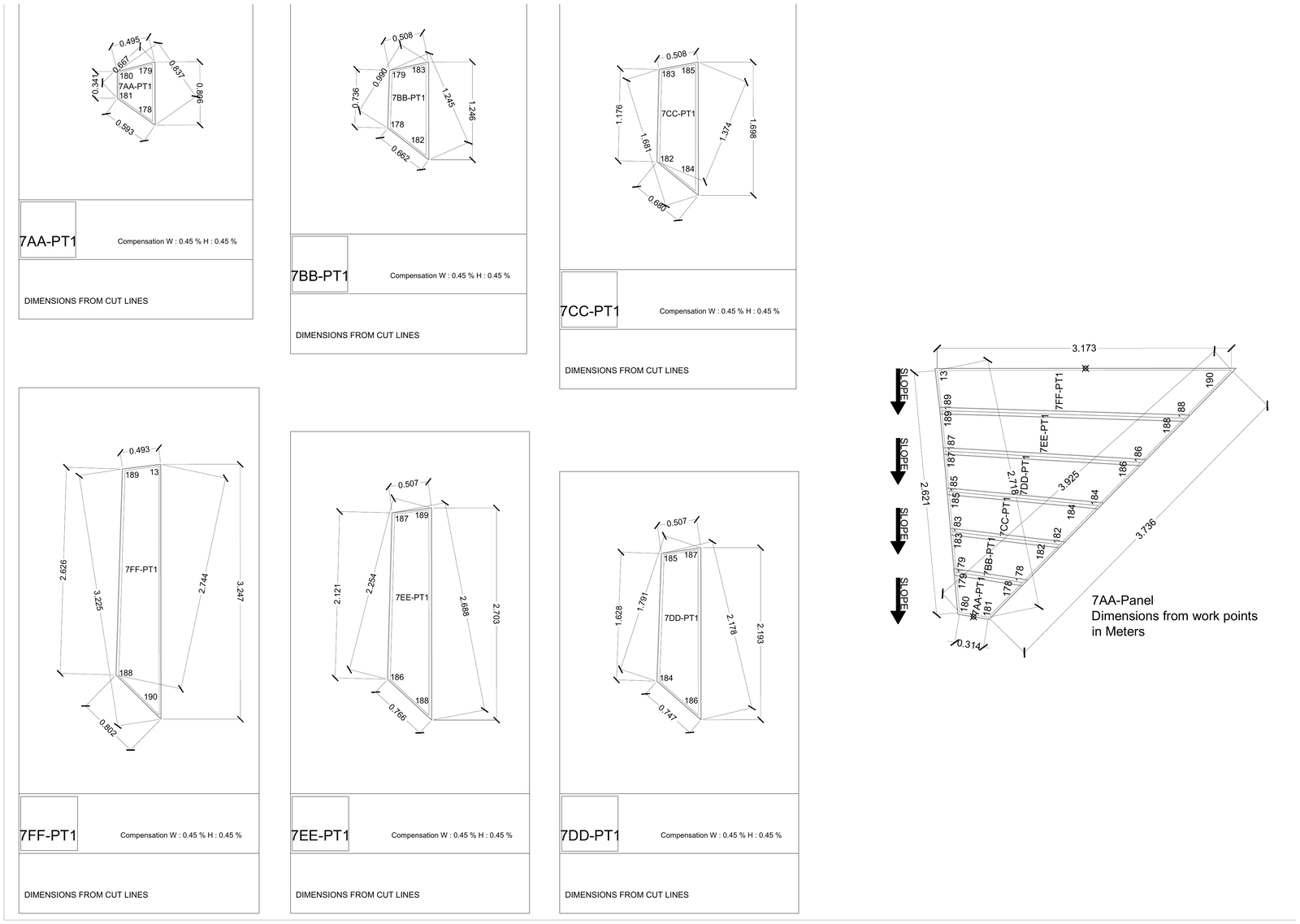
ETFE Panel Fabrication — Work Point Dimensions (Panel 7AA)

Fabrication drawing of the ETFE panels with the work point dimensions of each panel taken from the cut lines, in metres.
Panel work point dimensions — dimensions from cut lines, in metres

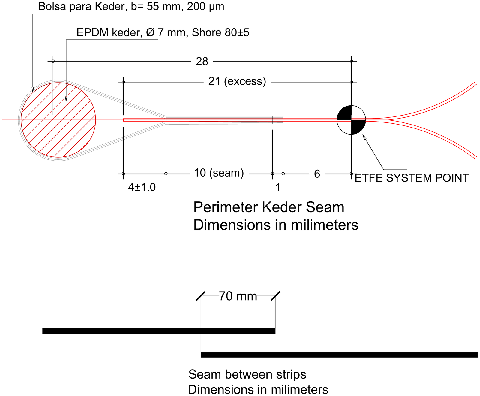
ETFE Panel Fabrication — Keder & Strip Seam Details

Detail drawing of the perimeter keder seam with the 55 mm keder pocket and the 7 mm EPDM keder, and of the 70 mm seam between foil strips.
Perimeter keder seam: pocket b = 55 mm, 200 µm · EPDM keder Ø 7 mm, Shore 80±5 · seam between strips 70 mm

Bill of Quantities — ETFE Panels & Aluminum Profiles

ETFE panels (1 of 2) — 9 rows
ETFE panels (1 of 2)
CodeDescriptionLength (m)UnitsQuantities
PANEL 1AETFE panel, color transparent with white printed patterning. Includes keder pocket for fixing to steel structure.piece1
PANEL 2AETFE panel, color transparent with white printed patterning. Includes keder pocket for fixing to steel structure.piece1
PANEL 3AETFE panel, color transparent with white printed patterning. Includes keder pocket for fixing to steel structure.piece1
PANEL 4AETFE panel, color transparent with white printed patterning. Includes keder pocket for fixing to steel structure.piece1
PANEL 5AETFE panel, color transparent with white printed patterning. Includes keder pocket for fixing to steel structure.piece1
PANEL 6AETFE panel, color transparent with white printed patterning. Includes keder pocket for fixing to steel structure.piece1
PANEL 7AETFE panel, color transparent with white printed patterning. Includes keder pocket for fixing to steel structure.piece1
PANEL 1AAETFE panel, color transparent with white printed patterning. Includes keder pocket for fixing to steel structure.piece1
PANEL 2AAETFE panel, color transparent with white printed patterning. Includes keder pocket for fixing to steel structure.piece1
ETFE panels & aluminum profiles (2 of 2) — 17 rows
ETFE panels & aluminum profiles (2 of 2)
CodeDescriptionLength (m)UnitsQuantities
PANEL 3AAETFE panel, color transparent with white printed patterning. Includes keder pocket for fixing to steel structure.piece1
PANEL 4AAETFE panel, color transparent with white printed patterning. Includes keder pocket for fixing to steel structure.piece1
PANEL 5AAETFE panel, color transparent with white printed patterning. Includes keder pocket for fixing to steel structure.piece1
PANEL 6AAETFE panel, color transparent with white printed patterning. Includes keder pocket for fixing to steel structure.piece1
PANEL 7AAETFE panel, color transparent with white printed patterning. Includes keder pocket for fixing to steel structure.piece1
T01_ALU_PROF_BASE-01Aluminum profile type BASE, for ETFE panel fixation.4.521piece2
T01_ALU_PROF_BASE-02Aluminum profile type BASE, for ETFE panel fixation.4.855piece2
T01_ALU_PROF_BASE-03Aluminum profile type BASE, for ETFE panel fixation.3.155piece2
T02_ALU_PROF_BASEAluminum profile type BASE, for ETFE panel fixation.2.771piece2
T03_ALU_PROF_BASEAluminum profile type BASE, for ETFE panel fixation.5.166piece2
T04_ALU_PROF_BASE-01Aluminum profile type BASE, for ETFE panel fixation.5.769piece1
T04_ALU_PROF_BASE-02Aluminum profile type BASE, for ETFE panel fixation.5.407piece1
T04_ALU_PROF_BASE-03Aluminum profile type BASE, for ETFE panel fixation.3.099piece1
T05_ALU_PROF_BASEAluminum profile type BASE, for ETFE panel fixation.3.894piece2
T06_ALU_PROF_BASEAluminum profile type BASE, for ETFE panel fixation.4.914piece2
T07_ALU_PROF_BASEAluminum profile type BASE, for ETFE panel fixation.3.542piece2
T08_ALU_PROF_BASEAluminum profile type BASE, for ETFE panel fixation.4.705piece2

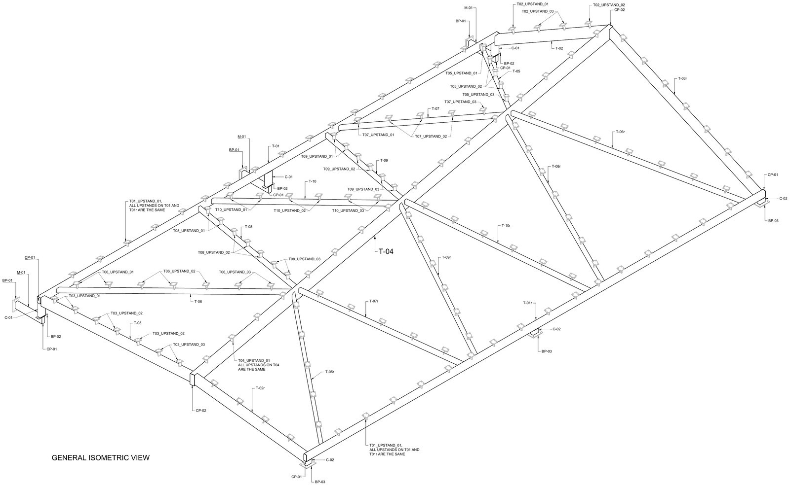
Structural Drawings — General Isometric View

General isometric structural drawing of the canopy frame with member marks and dimensions.
General isometric view

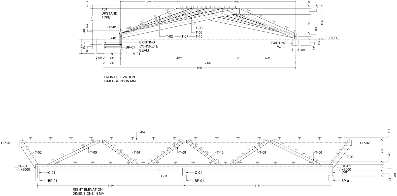
Structural Drawings — Front & Right Elevations

Front and right elevation drawings of the canopy, fully dimensioned in millimetres.
Front elevation and right elevation — dimensions in mm

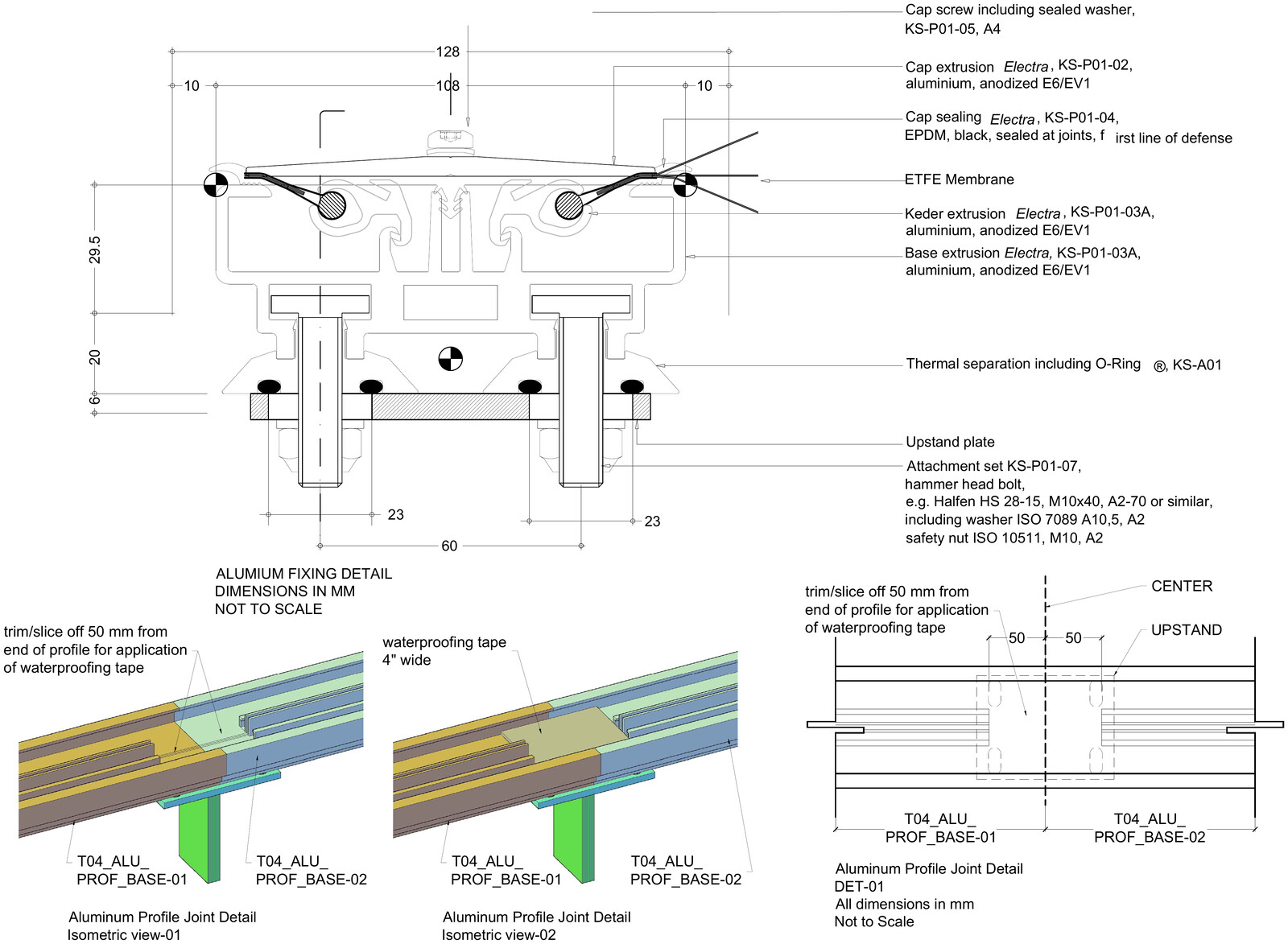
Aluminum Profile Fixing Detail — Joint & Waterproofing Detail

Section through the aluminium fixing detail showing the base and keder extrusions, the EPDM seal, the cap screw with sealed washer and the waterproofing tape at the upstand.
Aluminium fixing detail and profile joint detail — dimensions in mm

Similar project? Request a quote

Send us the area, the city and the fabric you need — we come back with a system and an indicative budget.

920011060 Sunday–Thursday, 07:30–17:00 We reply within one working day